Ri-1c Manual CADing Basics in Rhino


About this Tutorial
This course is intended for first time user of Rhino 3D and/or CADing as a subject. Self-taught users can also profit from the structure to consolidate essential concepts. There is a lot explaining while we create our first Manual CADing in Rhino, continuing our work of Modeling made in Ri-0a. By understanding the process to take the information from a 3D Model, and then manually tracing the shapes understanding the Line Thickness that will help us to understand the elements and its relevance in an architecture project. Finally scaling and placing it in the final paper sheet that will be printed to fully show it as a project.
Skill level and duration
Level: First Time Users
Duration: A couple of hours tops!
In this tutorial you will learn
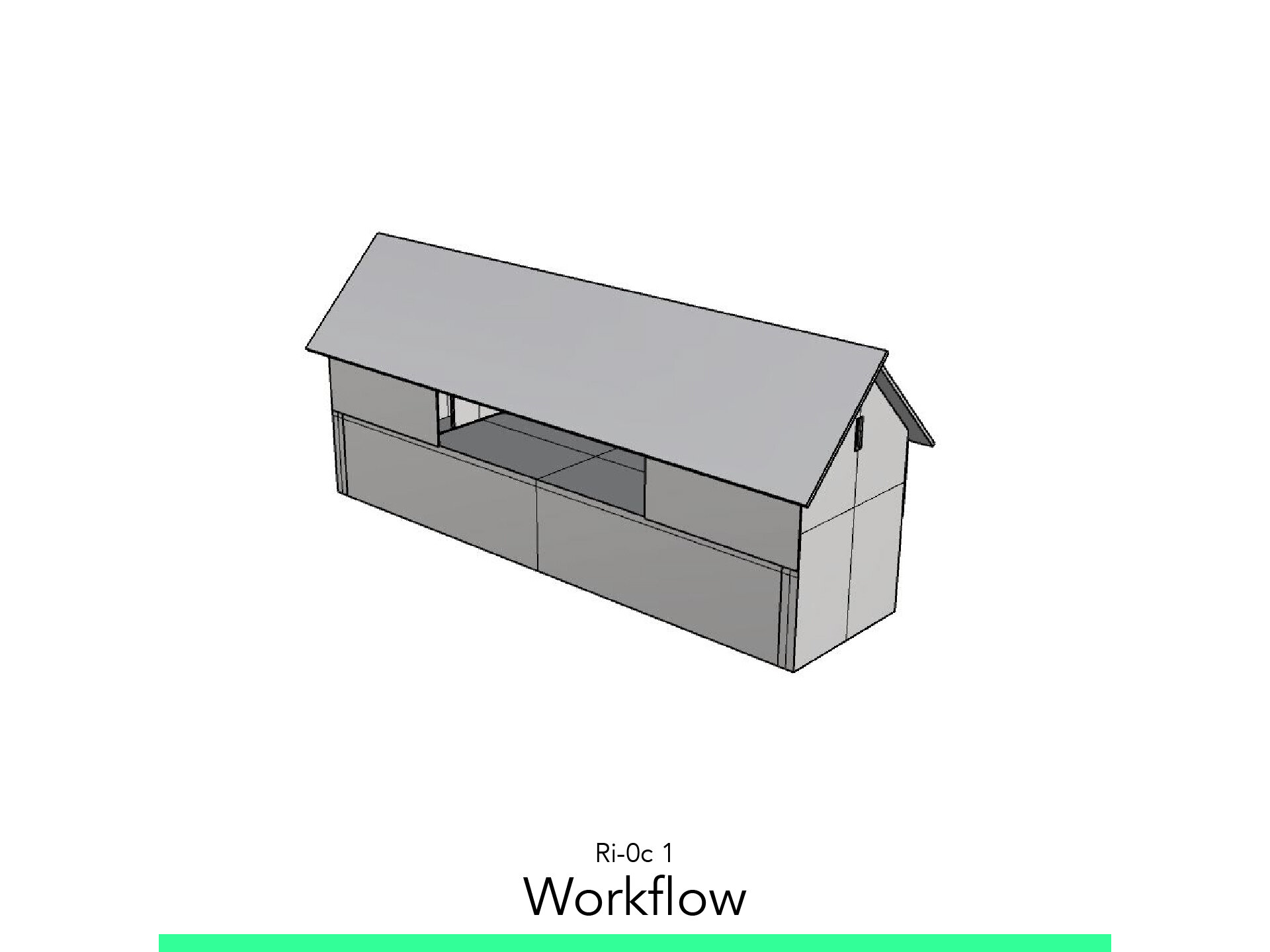
Workflow
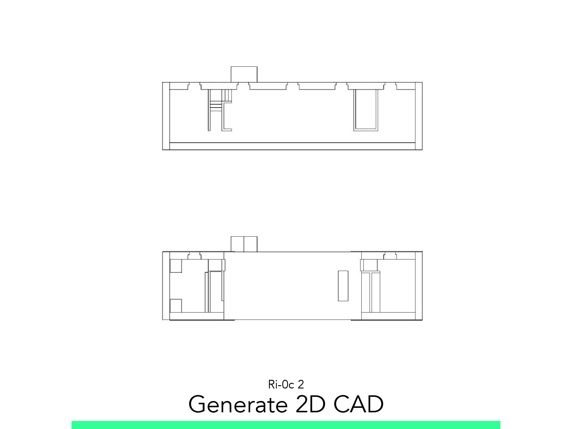
Generate 2D CAD
Layout
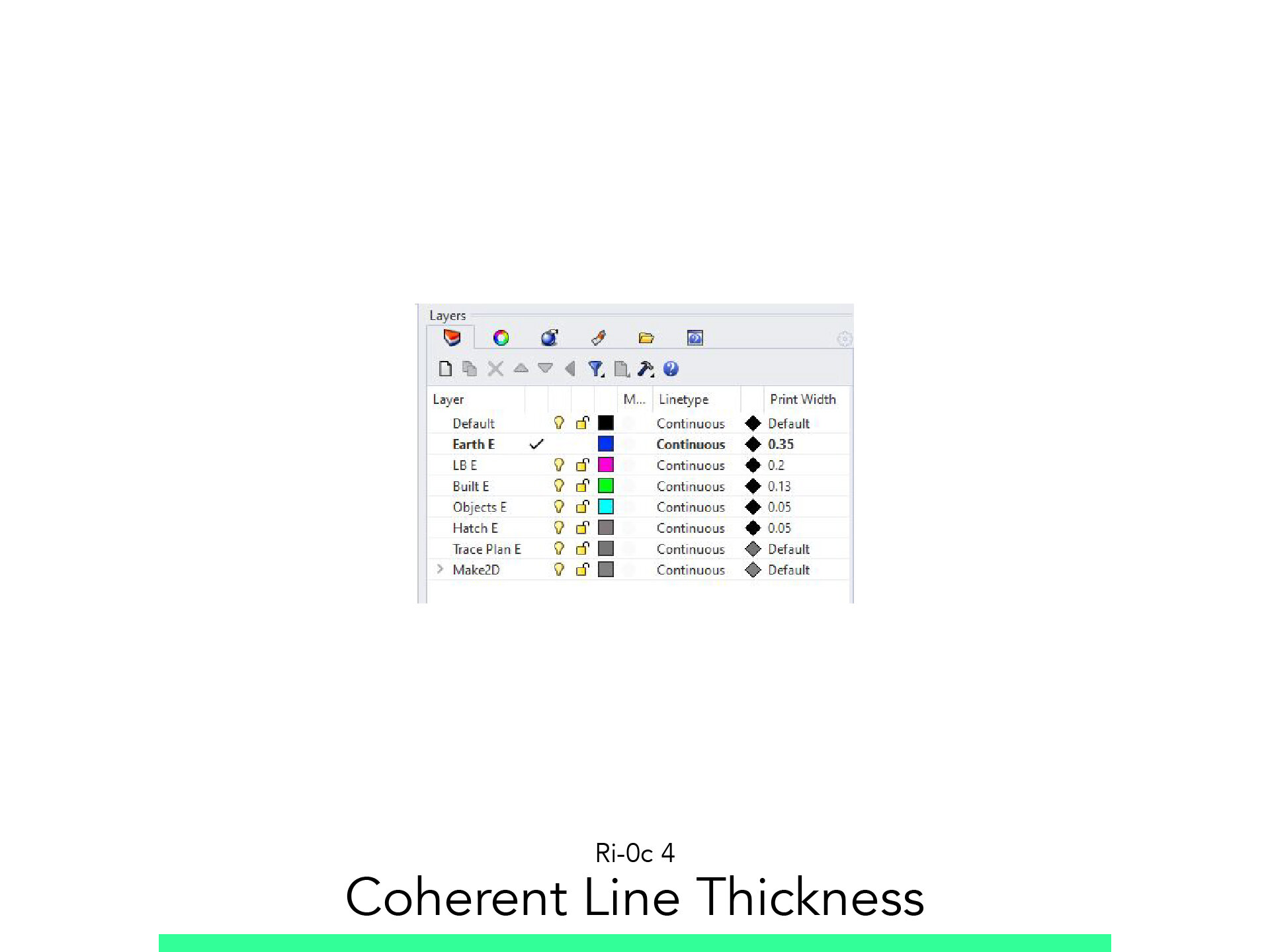
Coherent Line Thickness
Let’s CAD
Print Final
The materials you will need
Your laptop with internet connection to download and Install Software during the course.
Tutorial content
• 6 Videos
• Full Tutorial Script
• Sample 3D File
Why take this tutorial
This course its a good first step to learn how to extract information from a model to then modify it to create clear architecture plans. First learning the tools to create 2D from a 3D Model with Rhino, extracting the basic shapes that we are going to trace manually, but first learning what its the purpose and the use of the Line Weight in architecture projects by a clear and pedagogical way, to then draw it and trace it with more trust in the program. All this information will be concluded in the Layout to print it, to have a fully drawn architecture project with all the skills and ways of thinking learned in this tutorial.
1. Workflow

1.1. Generate 2D
The first step is to take the 3D Model we have created in the exercise Ri-0b and with great commands extract from it 2D CAD planes to use it and trace architecture plans.
1.2. Print
Then we are going to start the Layout sketch to view how are we going to present it.
1.3. Sketch by line type
Finally, we are going to establish the line thickness, color and category to know how we are going to trace over the 2D CAD we made from the 3D Model.
1.4. Start the CAD!
Now let’s align our mantras to start this quest of drawing our architecture plans.
2. Generate 2D CAD

2.1. Floorplans
Start command _ClippingPlane
Trace the Rectangle in the Top View.
_Move the ClippingPlane in the Back View to cut the First Floor.
Select the Clipping Plane and check to se it in: Perspective
Select the Building and start command _Make2D
A window will appear and check it is in View: Top.
Press Ok and it will appear the 2D TRace near the Point 0 of the model.
Do the 1 to 7 steps again for the Second Floor.
2.2. Section
Start command _ClippinPlane
To make Vertical Clipping Line select: Vertical
Trace the Rectangle in the Perspective View.
_Move the ClippingPlane in the Back View to cut the Building.
Select the Clipping Plane and check to see it in: Perspective.
Flip the Clipping Plane.
Select the Building and start command _Make2D.
A Window will appear and check it is in the View: Right.
Press Ok and it will appear the 2D Trace near the Point 0 of the Plan.
2.3. Facade
Select the Building and start command _Make2D.
A Window will appear and check it is in the View: Right.
Press Ok and it will appear the 2D Trace near the Point 0 of the Plan.
2.4. Perspective View
Start command _ClippinPlane
To make Vertical Clipping Line select: Vertical
Flip the Clipping Plane.
Trace the Rectangle in the Right View.
_Move the ClippingPlane in the Back View to cut the Building.
Select the Clipping Plane and check to see it in: Perspective.
Start command _OrientCameraToSrf.
To change the appereance on the view: View Arrow > Shaded.
Start command _ViewportProperties.
Change Camera Lens Length to 35.0
To Create a View start command: _NamedView.
Click to Save the New View as Dinning.
Select the Building and start command _Make2D.
A Window will appear and check it is in the View: Dinning.
Press Ok and it will appear the 2D Trace near the Point 0 of the Plan.
2.5. Change Layers
Create a New Layer for the Trace Plan.
Go to Layer’s Tab on the right side of the Screen and change the color of the New Layer to Grey in the Square, next to the Padlock.
Take the 2D Created and start command _ChangeLayer.
Select the New Layer.
Go to the Properties Tab and Change Display Color to: By Layer.
Go to Layer’s Tab on the right side of the Screen and Lock the Padlock.
2.5. Layout Trace
Before you start embarking on a slopy crusade you first need to think about the objective of the drawings you are going to show and what you want to express.
Draw the square of the A3 Size with _Polyline: 0.297x0.42
_Scale the square to 100.
Fit all the Drawings you have just created in the Square.
3. Layout

3.1. Paper Space
Organize the drawings as the position of the Layout.
Star command _Layout.
Select Rhino PDF as Printer.
Select A3 - Landscape as Size.
´Press OK.
It will take you to the Paper Layout View.
Go to the Properties Tab, and set 1:100 Scale:
Layout = 1.00 mm
Model = 100.00 cm
To Print start command _Print.
4. Coherent Line Thickness

4.1. Set Layer 1 Earth
Go to the Layer Tab at the right side of the screen.
Click on the New Layer Icon.
Write the Name of the Layer: Earth.
Change the Layer Print Color to 255 Black. (The Diamond Icon)
Change the Layer Print Width from Default to: 0.35.
4.2. Set Layer 2 Load-Bearing
Go to the Layer Tab at the right side of the screen.
Click on the New Layer Icon.
Write the Name of the Layer: Load-Bearing.
Change the Layer Print Color to 255 Black. (The Diamond Icon)
Change the Layer Print Width from Default to: 0.20.
4.3. Set Layer 3 Built
Go to the Layer Tab at the right side of the screen.
Click on the New Layer Icon.
Write the Name of the Layer: Built.
Change the Layer Print Color to 255 Black. (The Diamond Icon)
Change the Layer Print Width from Default to: 0.13.
4.4. Set Layer 4 Objects
Go to the Layer Tab at the right side of the screen.
Click on the New Layer Icon.
Write the Name of the Layer: Objects.
Change the Layer Print Color to 255 Black. (The Diamond Icon)
Change the Layer Print Width from Default to: 0.05.
4.5. Set Layer 5 Hatch
Go to the Layer Tab at the right side of the screen.
Click on the New Layer Icon.
Write the Name of the Layer: Hatch.
Change the Layer Print Color to 255 Black. (The Diamond Icon)
Change the Layer Print Width from Default to: 0.05.
5. Let’s CAD

5.1. Earth
Using CAD Tools:
_Polyline to trace the Terrain.
Using CAD Modifiers:
_Trim to erase the First Floor on the Elevation.
Check you Sketch, think… and Draw!
5.2. Load-Bearing
Using CAD Tools:
_Polyline to trace the Terrain.
_SmartTrack to use border reference.
Using CAD Modifiers:
_Array to create the ceiling structure.
Check you Sketch, think… and Draw!
5.3. Projected Built
Using CAD Tools:
_Polyline to trace the Terrain.
_SmartTrack to use border reference.
Using CAD Modifiers:
_Offset to create window glass.
_Copy to repeat the same window.
_Mirror to reflect the Big Windows.
_PointsOn to modify created shapes.
Check you Sketch, think… and Draw!
5.4. Projected Objects
Using CAD Tools:
_Polyline to trace the Walls that we cut.
_SmartTrack to use border reference.
Using CAD Modifiers:
_Array to create the closet divisions.
Check you Sketch, think… and Draw!
5.5. Hatches
Using CAD Tools:
_Hatch to create hatches.
Using CAD Modifiers:
_Array to create the ceiling structure.
Check you Sketch, think… and Draw!
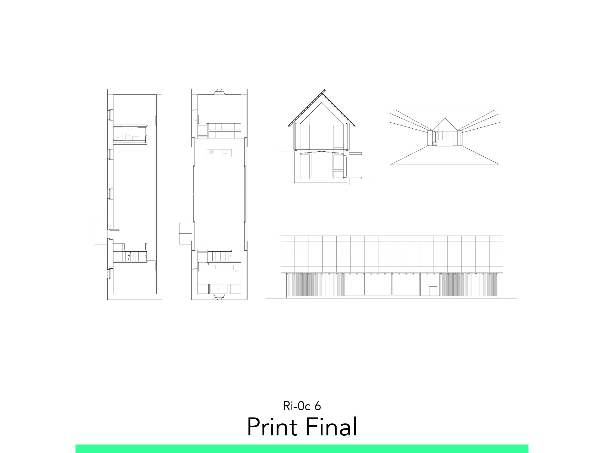
6. Print Final

6.1. Update Layout
Go to the Layout Tab.
Update and Rearray the Views.
Start command _PrintDisplay to see true Line Weight.
Verify the Scale.
Hide the Trace Layer.
Verify the Scale of the Hatches.
Start command _Text to add Text.
To Print Start command _Print.
Follow your study path with these recommended tutorials


Model in ArchiCAD for the absolute first time with me!
Let me teach you basic commands of the software for you to be ready work on your projects. Start from the very basics and follow me step-by-step in the process of giving more detail to your architectural model.