AC-1a Modeling Basics


About this Tutorial
This course is intended for first time users of ArchiCAD or/and Modeling. Self-taught users can also profit from the structure to consolidate essential concepts. Here we will learn the tools that will help us to express our project, from the most basic shapes inserted into the context, to all the elements of the constructive detail of a facade. We will also be learning some of the tools needed to get from basic sketches to a full modeled architecture project.
Skill level and duration
Level: First Time Users
Duration: A couple of hours
In this tutorial you will learn
Overview
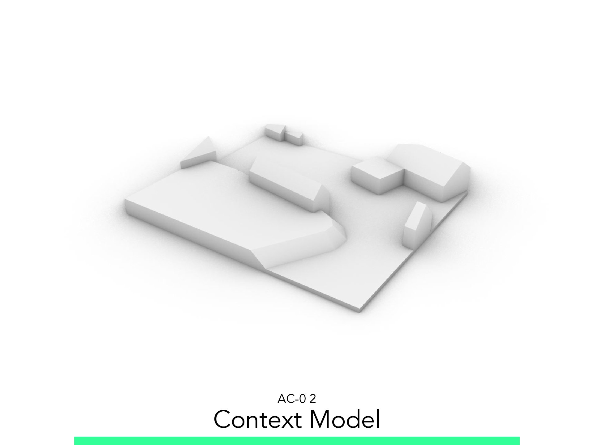
Context Model
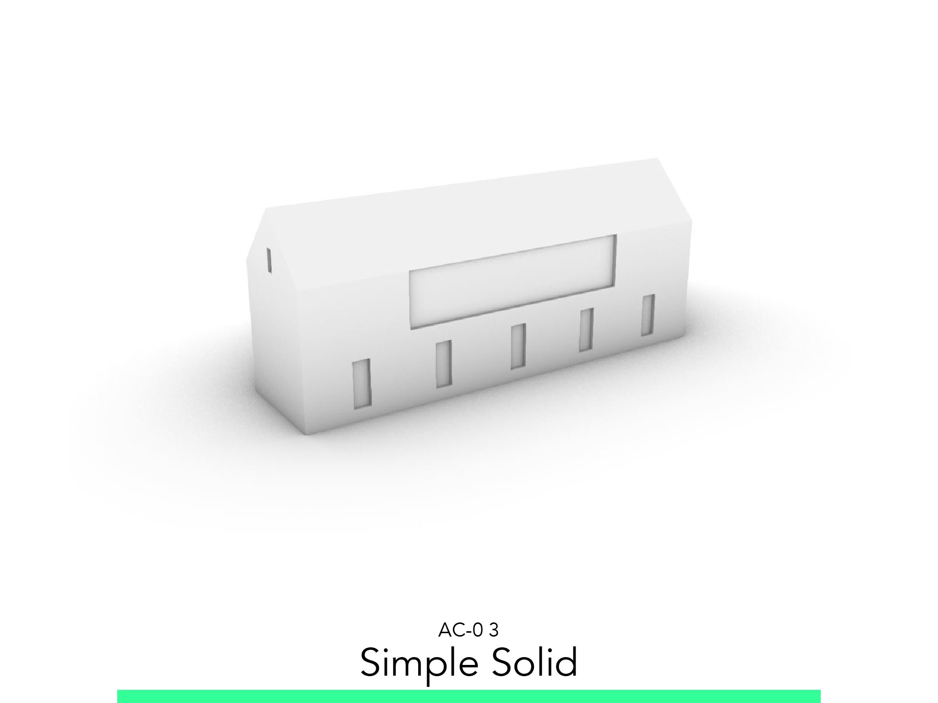
Simple Solid
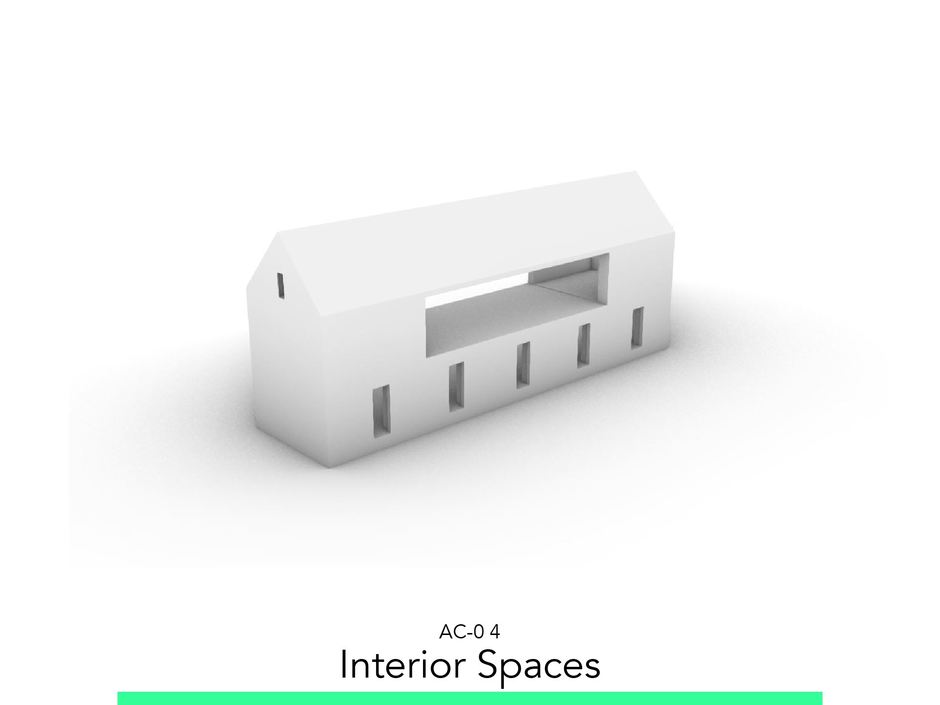
Interior Spaces
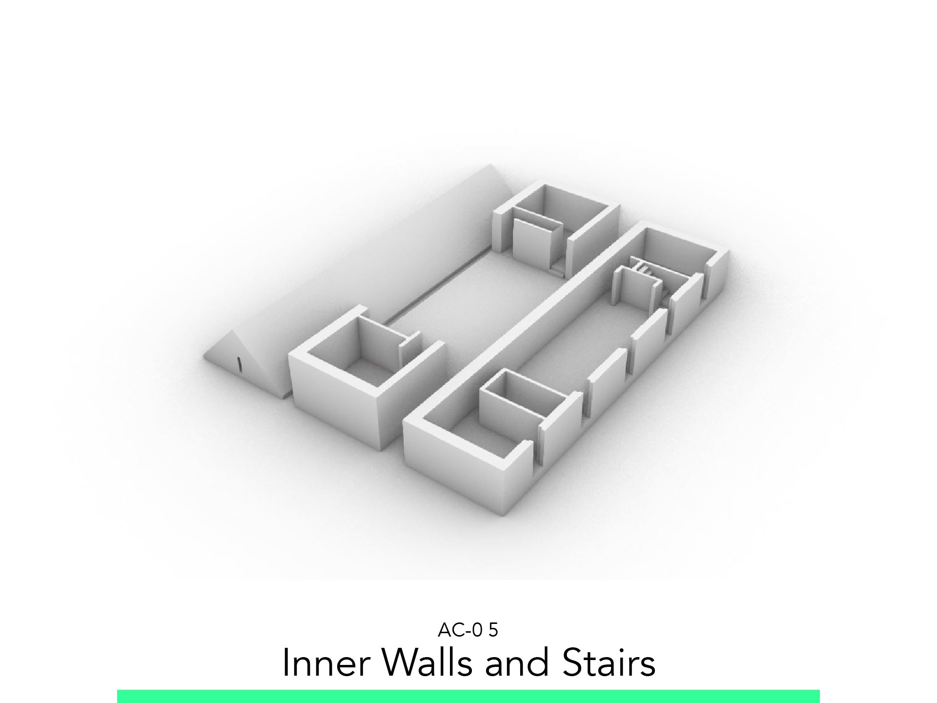
Inner Walls and Stairs
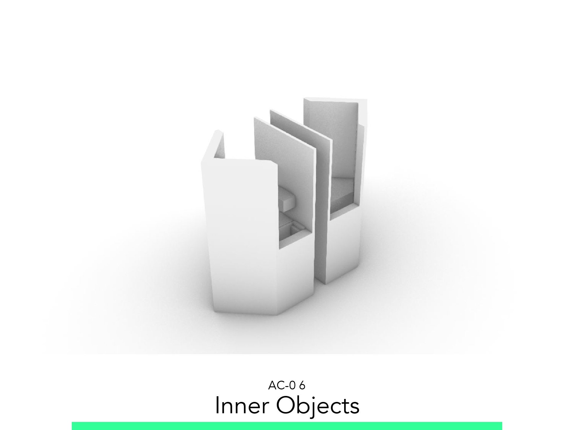
Inner Objects
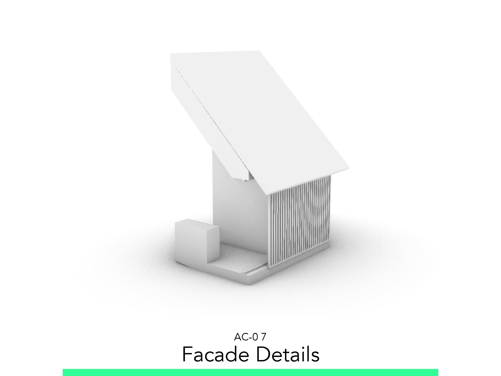
Facade Details
The materials you will need
Your laptop with internet connection to download and Install Software during the course.
Tutorial content
• 7 Videos
• Full Tutorial Script
• Sample 3D Printable File
Why take this tutorial
Modeling is the basic process of ArchiCAD, with this you can produce the base so you can later render, CAD and document. In this tutorial you will learn to use several tools to be able to model a project from zero to a specific detail of a facade. This is a great introduction to ArchiCAD and a platform to discover the benefits of using it. After this tutorial, you can start to learn about rendering, CADing and feel more confident to develop your architectural project.
1. Overview
You must always balance the time spent in a task with power it will provide to the project’s representation. To do this, it is recommended to think about your design in different levels of detail, each being a coherent step after which you will generate a model you can use along with the relevant details for whichever phase you are in.
2. Context Model

2.1. Create Topography
Go to the Ground Floor.
To create the base Start Command: Toolbar > Morph
Adjust the Following Settings:
Structure: GENERIC – STRUCTURAL
Geometry Method: Box
Draw the two Topographic levels: Pet Palette (PP) > Add Polyline
Go to 3D View, and move the polylines created:
PP > Offset Edge
PP> Move Node
2.2. Create Context
Go to the 3D View.
To create the base Start Command: Toolbar > Morph
Adjust the Following Settings:
Structure: GENERIC – STRUCTURAL
Geometry Method: 3 Points
Trace the middle of the Roof: PP > Add Polyline
Move the Roof sides: PP > Offset Edge
Go to the Ground Floor.
To Split the Buildings: Edit > Reshape > Split
Select one building.
Start command.
Select the border line.
Select the Outside side of the building.
2.3. Export STL
Go to the 3D View.
Isolate the Model F5
Save as: STL
Define the Scale 1:500
3. Simple Solid

3.1. Insert Picture
Go to the Worksheet.
Create a New Worksheet for Plans on the Project Map.
Go to File > External Content > Place External Drawing.
Import the plan and section JPEG.
Place it on the Worksheet.
To Scale the plan: Edit > Reshape > Resize
Or you can use the Shortcut. Ctrl+ K
3.2. Basic Volume
Go to the Ground Floor.
Draw a Solid with the plan measure and set height according to the section.
Extrusion Length: 5.40.
Go to the 3D View.
In 3D Window Add a Polyline to create the Roof.
Move the Edges to create the Roof: 2.60.
Go to the Ground Floor.
Measure the Height and Elevation of the Windows.
Create a Morph based on the plan openings and set the Elevation you have just measure.
Set its Elevation in the Morph Properties.
Go to the 3D View.
Open Solid Element Operation.
Select the Building as Target.
Select the Window Solids as Operators.
Choose Operation: Subtraction
Move and hide the Operators to layer 119 Operator
3.3. Export STL
Go to the 3D View.
Isolate the Model F5
Save as: STL
Define the Scale 1:200
4. Interior Spaces

4.1. Walls
Go to the Ground Floor.
To Trace Walls in the plan: ToolBox > Walls.
You can create as Geometry Method: Rectangular
Adjust the Following Settings
Home Story: 0. Ground Floor
Wall Top: 1. Story (Home + 1)
Wall Thickness 0,50
Draw the Rectangle as in the Reference Plan
Go to the 1. Story.
To Trace 1. Story Walls in the plan: ToolBox > Walls
You can create as Geometry Method: Rectangular
Adjust the Following Settings:
Home Story: 1. Story
Wall Top: 2. Story (Home + 1)
Wall Thickness: 0,50
Draw the Rectangle as the one of the Ground Floor.
4.2. Roof
Go to the 3D View.
To Create a Roof: Toolbox > Roof
Select as Geometry Method: Multi-Plan
Select as Construction Method: Rotated Rect. Hip Gable
Adjust the Following Settings:
Structure: ST- Generic Structural
Thickness: 0.50
Eaves Overhang: 0.00
Roof Edge Angle: 45.00°
Home Story: 2. Story
To project Zero: 4.90
Edge Angle: 45.00°
Elevate the 1. Story Wall to be over the Roof.
Start Solid Element Operation.
Select Walls as Target.
Select the Roof as Operator.
Choose Operation: _Subtraction with Upward Extrusion
4.3. Ground Floor Windows
Go to the Ground Floor.
To Create Windows over the Walls: Toolbox > Window
In Properties select as Element: Simple Window Opening
Place it Over the Wall.
Size: 1.00 x 2.00
Sill: 0.15
4.4. 1 Story Openings
Go to the 1. Story.
To Create Windows over the Walls: Toolbox > Door
Adjust the following settings:
In Properties select as Element: Simple Door Opening
Place it Over the Wall.
Size: 10.60 x 2.50
Sill: 0.00
To Create Windows over the Walls: Toolbox > Door
Adjust the following settings
In Properties select as Element: Simple Window Opening
Place it Over the Wall
Size: 0.50 x 1.00
Sill: 2.70
4.5. Slabs
Go to the 3D View.
To Create Slabs: Toolbox > Slab
Bottom and Top of First Slab: 0.45 x 0.00
Bottom and Top of Second Slab: 0.45 x 3.30
4.6. Export STL
Go to the 3D View.
Isolate the Model F5
Save as: STL
Define the Scale 1:200
5. Inner Walls and Stairs

5.1. Ground Floor Inner Walls
Go to the Ground Floor.
To create inner Walls: Toolbox > Walls
Adjust the following settings:
Wall Thickness: 0.17
Try to make of make a Distance from other walls: 0.90
Side of Stairs Wall Thickness: 0.10
5.2. 1 Story Inside Walls
Go to the 1. Story.
To create inner Walls: Toolbox > Walls
Adjust the following settings:
Wall Thickness: 0.17
Try to make of make a Distance from: 0.90
Start Solid Element Operation to delete the walls over the roof.
Select Walls as Target.
Select the Roof as Operator.
Choose Operation Subtraction with Upward Extrusion.
5.3. Stairs
Go to the Ground Floor.
To create Stairs: Toolbox > Stairs
Adjust the following settings:
Number of Stairs: 15
Height of Stair: 0.22
Stairs Depth: 0.25
Open Hole in the Slab: PP > Subtract from Polygon
5.4. Export STL
Go to the 3D View.
To Create our 3 Floors Model:
Separate our Ground Floor.
Copy our 1. Story and Roof.
Delete the Roof and fit the Inner Walls on the outside Walls border.
In the Second Copy we use the Roof as Operator of the Inside Walls.
Isolate the Model F5
Save as: STL
Define the Scale 1:200
6. Inner Objects

6.1. Kitchen and Closets
Go to the 1. Story.
Start a Slab to trace the objects. Toolbox > Slab.
Modify sizes in the 3D Window.
Use Solid Element Operation to fit the Kitchen Drawers.
6.2. Export STL
Go to the 3D View.
To Create our 1. Story Model:
Erase the Ground Floor.
Move and Copy the 1. Story and Roof.
Create a Morph to Subtract the half of the two copies.
Start Solid Element Operation and Subtract with the Solid all the Building.
Convert Selection to Morph.
Isolate the Model F5
Save as: STL
Define the Scale 1:100
7. Facade Details

7.1. Entrance
Create Solids for entrance ceiling and base. ToolBox > Solid
Go to the Ground Floor.
Create the solid drawing to then extrude it in 3D.
Go to the 3D View.
Move it and Rotate it in the Building.
Create a Slab of the Entrance. ToolBox > Slab
7.2. Wood Facade
Go to the 3D View.
Create a Roof to cover the building. ToolBox > Roof.
Adjust the following settings:
Geometry Method: Multiplane
Construction Method: Rotated Rectangular
Thickness: 0.22
Eaves Overhang > Offset: 0.60
Go to the 1. Story.
Create the Wood Frame’s Wall. ToolBox > Wall
Create the wall that occupies one frame
Create the Wood Frame. ToolBox > Door
Adjust the following settings:
Element: Pocket Door 22
Size: 4.99 x 2.50
Sill: -0.20
Properties > Sliding Door Settings > Door Leaf Type
Frame Width: 0.05 x 0.05 x 0.05
Grid: 0.05 x 0.05
Panels Number: V = 1, H = 50
7.3. Export STL
Go to the 1. Story.
To Create our 1. Story Model:
Erase the Ground Floor.
Move and Copy the 1. Story and Roof.
Create a Morph to Subtract the half of the two copies.
Start Solid Element Operation and Subtract with the Solid all the Building.
Convert Selection to Morph.
Isolate the Model F5
Save as: STL
Define the Scale 1:50


Model in ArchiCAD for the absolute first time with me!
Let me teach you basic commands of the software for you to be ready work on your projects. Start from the very basics and follow me step-by-step in the process of giving more detail to your architectural model.