AC-2b Context Model - Mesh


About this Tutorial
This course is intended for intermediates of ArchiCAD or/and Modeling as a subject. Self-taught users can also profit from the structure to consolidate intermediate concepts. Here you will learn the skills and tools to take a simple context model to a expressive and true topography, not only in model but also ready to be 3D Printed. Thinking all the time in the model and the project not just digitally but also physically.
Skill level and duration
Level: Intermediate Users
Duration: A couple of hours tops!
In this tutorial you will learn
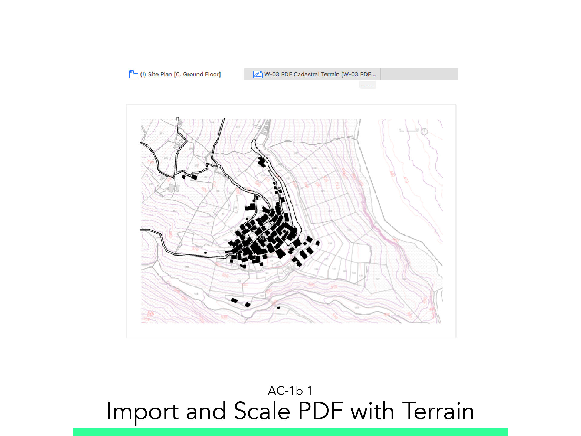
Import and Scale PDF with Terrain
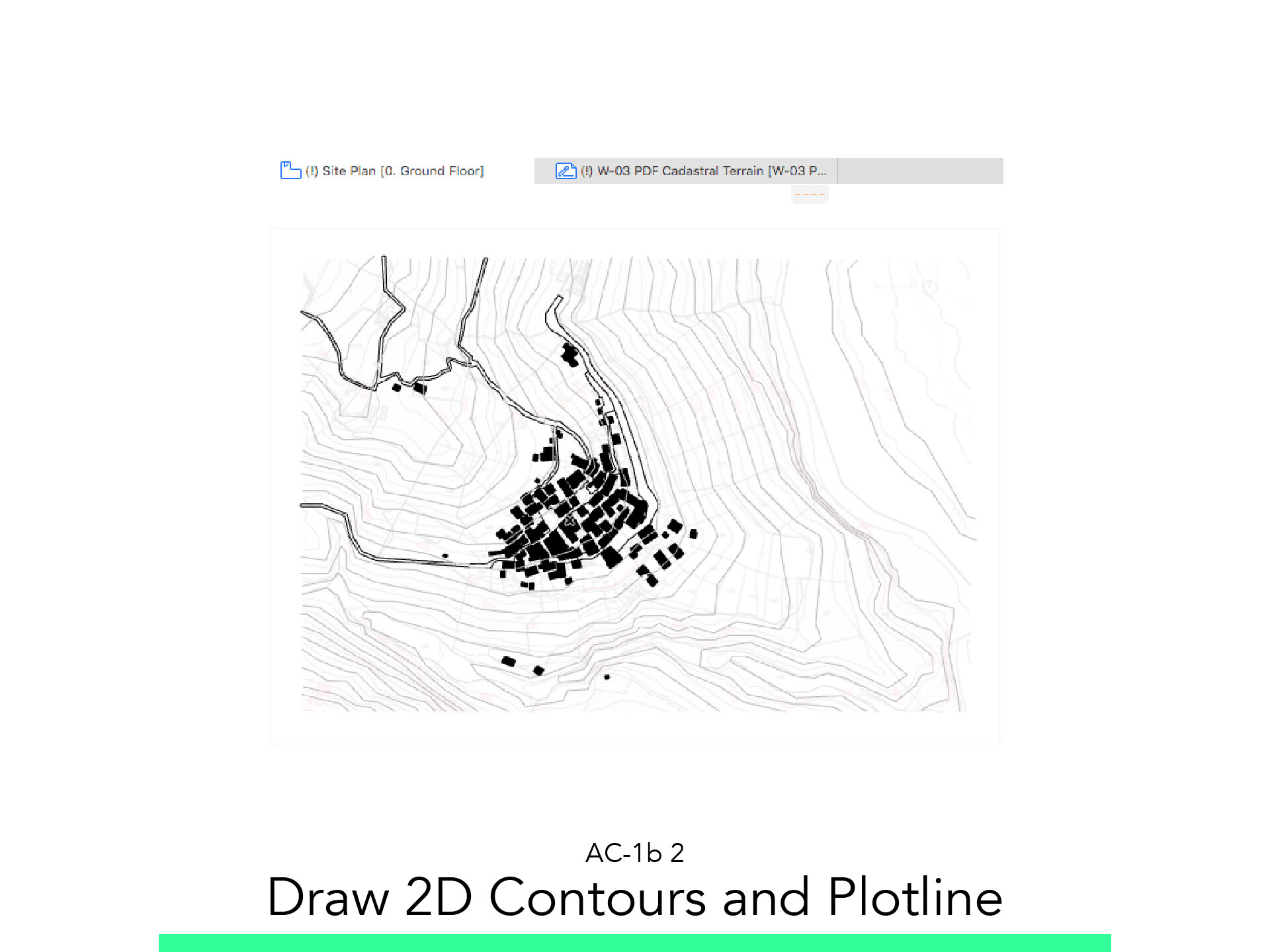
Draw Two Contours and Plotline
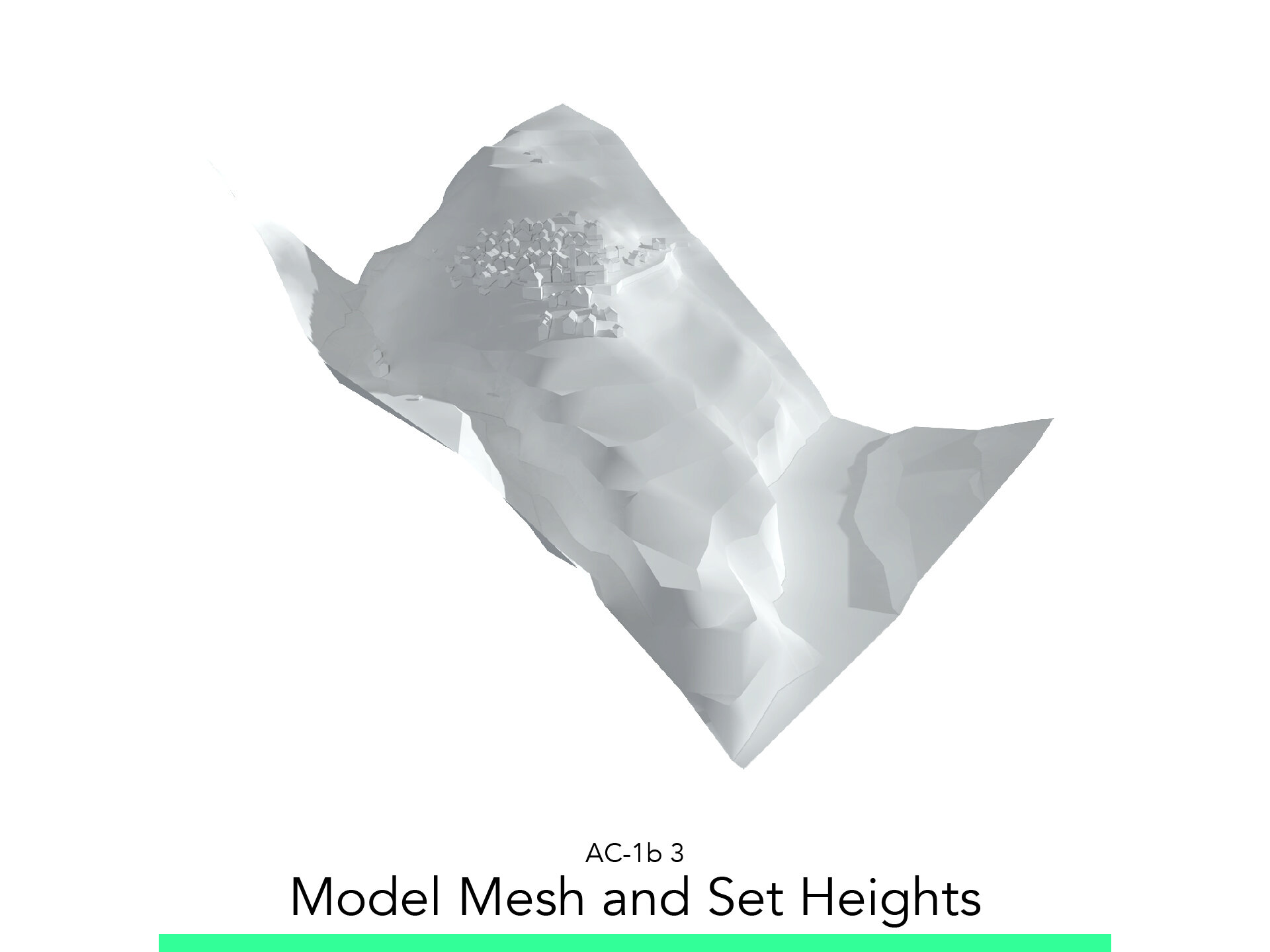
Model Mesh and Set Heights
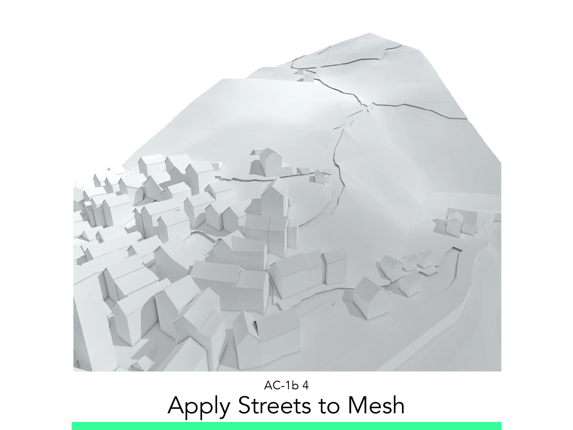
Apply Streets to Mesh
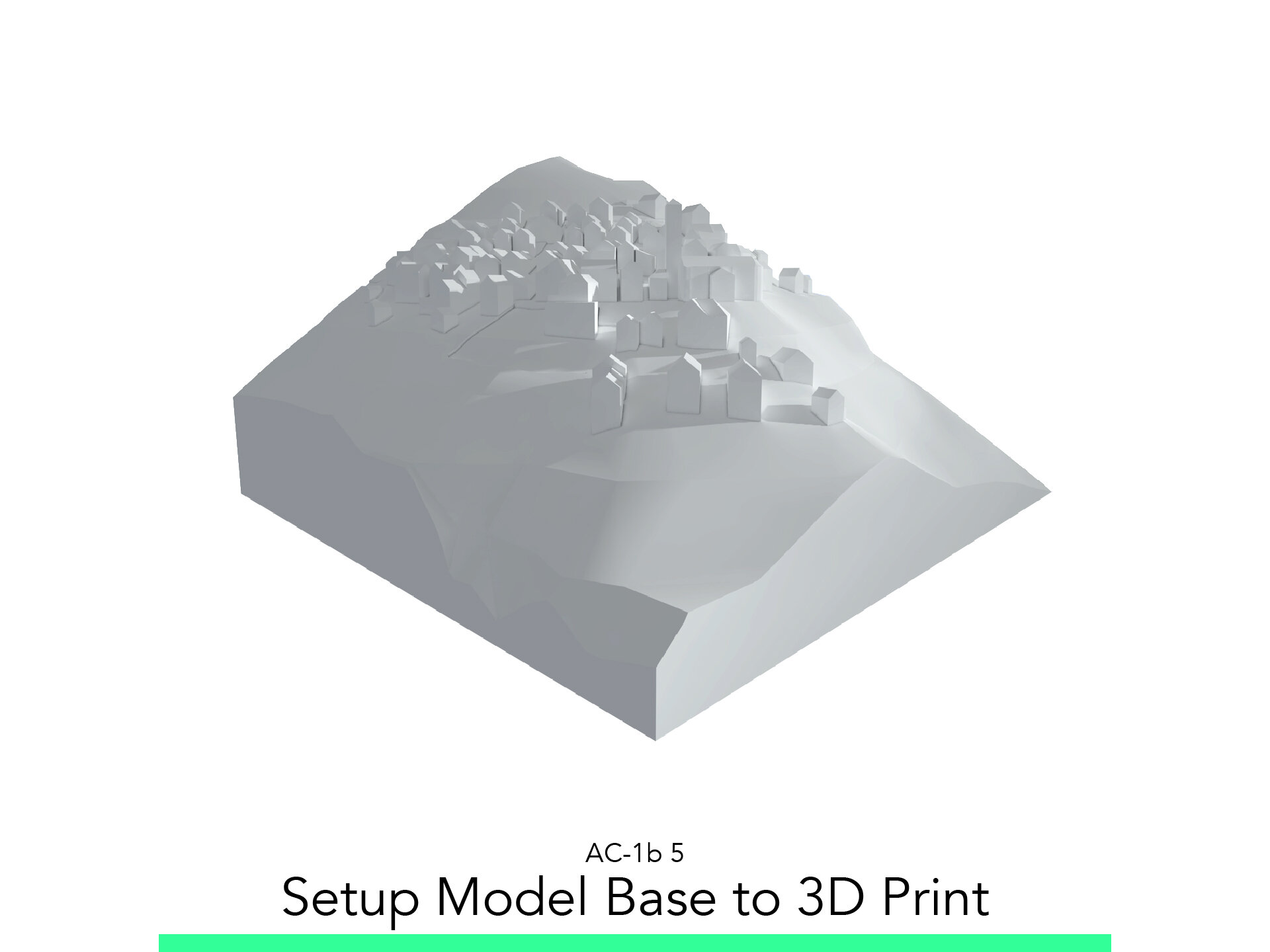
Setup Model Base to 3D Print
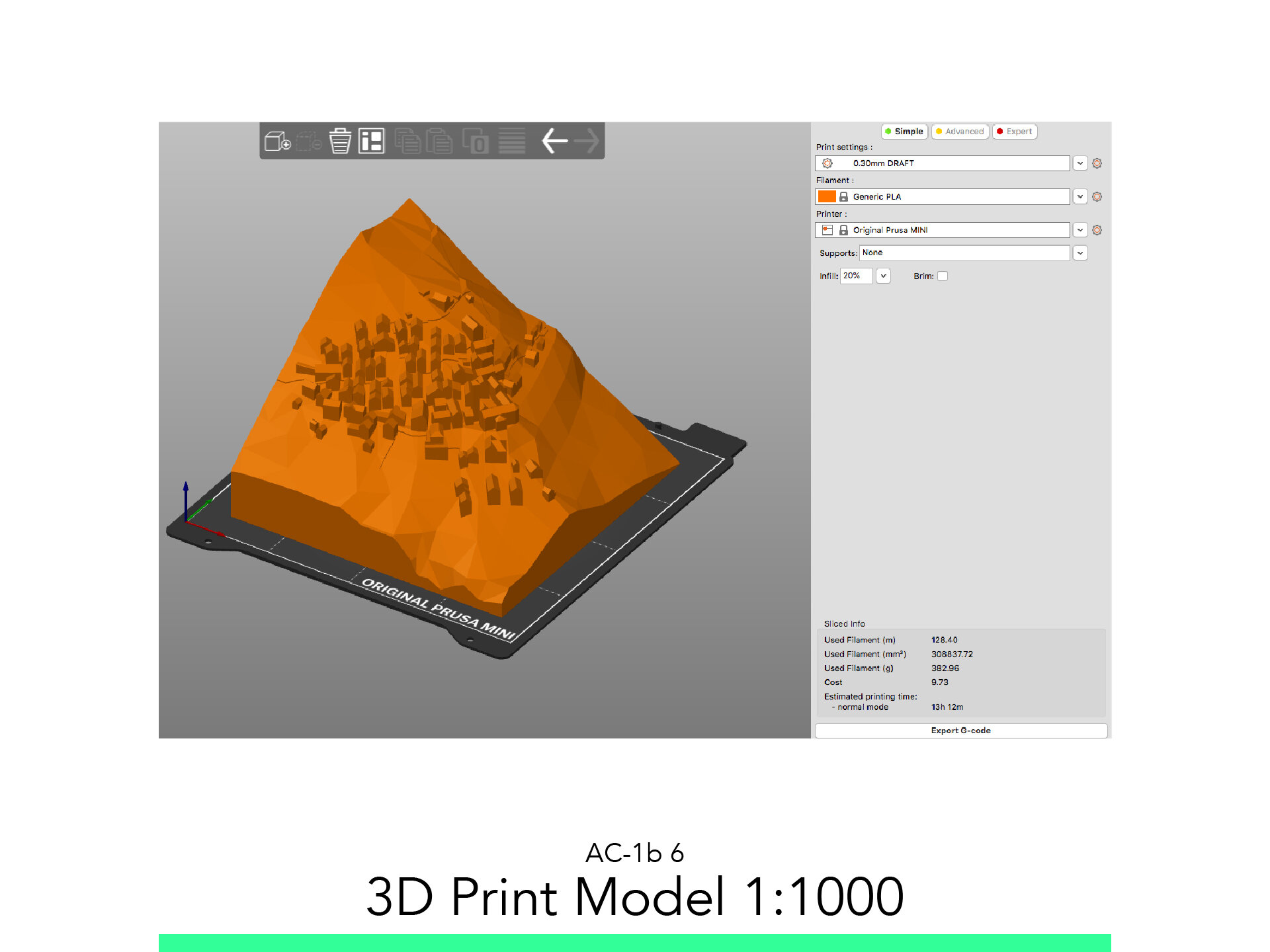
3D Print Model 1:1000
The materials you will need
Your laptop with internet connection to download and Install Software during the course.
Tutorial content
• 6 Videos
• Full Tutorial Script
• Sample 3D File
Why take this tutorial
Here you will learn to really use the Mesh Tool, how to take 2D information like topographic lines and shape the mesh by those. You will learn how to fully model a complex topography in ArchiCAD and also to accomodate the context buildings that are localized there. And as the top of the cake, you can also take the model to fully 3D print it, and make an awesome presentation of the context around your incredible model that you could also learn later with us. This is a very useful skill that will be of great help for any architect.
1. Import and Scale PDF with Terrain

1.1. New Worksheet
In the Project Map create a new Worksheet named PDF Cadastral Terrain.
1.2. Insert PDF
Drag and Drop the PDF File from the AC-1b_Links folder provided.
1.3. Change Layer
Select the image and change its Layer to 101 Reference Vector.
1.4. Position the Image
Using Drag: Ctrl+D and Rotate: Ctrl+E command position the image as close to the origin possible.
1.5. Resize
Go to the Menu > Edit > Reshape > Resize to start the Resize command or use Ctrl+K.
Click on the 0 of the graphic scale of the image.
Click on the 25 of the same graphic scale.
Enter the value in Meter there should be between those two points. 25.
Rotate the image to make North point straight upward.
1.6. Set Scale
Set the Scale of the Worksheet to 1:1000.
1.7. Save Current View
From the View Map > Right Click on the Folder Context and select Save Current View and Leave the default name.
1.8. Show as Trace Reference
From the same View Folder Right Click on Site Plan.
Select Show as Trace Reference.
Select the PDF and Drag to match the position of your model.
2. Draw 2D Contours and Plotline

2.1. Draw High Lines
From the view map double click on Site Plan.
Right-Click on the View W-03 PDF Terrain and select Show as Trace Reference (Make Sure Images are Visible).
Start the “Polygon” Command and adjust the following settings:
Layer: 134 Height Lines.
Pen: 182.
Start drawing the Height Lines every 10m trying always to do as few points as possible not to end up with a high polygon mesh.
Be mindful of what your are modeling, and detach yourself for the rigorousness of the CAD and think plasticly. Maybe not in your first mesh, but is something to consider as you do this more regularly.
2.2. Model Plotline
Start the Slab command and adjust the following settings:
Layer: 141 Plotline.
Reference Point: Top.
Structure: Simple.
Bottom and Top: 0.15 and 0.00.
Pen Uncut: 241.
Surface: 1-1.
2.3. Main Street
Model the Main Street as a Building using Favorites:
Change the Reference line to Top.
3. Model Mesh and Set Heights

3.1. Model Mesh
Start the “Mesh” command and adjust the following settings:
Layer: 110 Terrain Mesh.
Geometry Method: Rectangle.
Structure: Mesh.
Bottom Top: -150m.
Model Ridges: All Ridges Smooth.
Cover Fill Pen: 182.
Cover Fill Background Pen: 0.
Surface: 3-3.
Model Mesh.
Go to the 3D Videw to check progress.
3.2. Imprint Height Lines
Imprint the Height Lines onto the Mesh.
Select the Mesh.
Activate the Mesh command.
Hold the Space Bar down.
Click on the First Line.
Select Fit to Users Ridges.
Repeat until the whole mesh has been imprinted.
Check Result in the 3D Window.
3.3. Set the Heights
Draw your Zero Line and change its pen to: 242 and imprint it into the terrain as well.
Turn the Layer 108 Height Lines.
Click on one of your Zero Line vertices to select it.
Click again to get the Pet Palette of it.
Click on set the Z Height.
Set the Height to 0.
Set: To Project Zero.
Check the Apply to All box.
Check Result in the 3D Window.
Set the rest of the Heights in relation to your Zero repeating the before mentioned steps.
Check the Model and Redefine the View.
Pull the corners up.
3.4. Adjust Building Position
From the 3D Window, turn the Layer 104 as well to move the buildings with their respective roof to the terrain.
Adjust the Height of the Roof as well.
3.5. Save Current View
From the “View Map” right click the “Context” folder and select: Save Current View.
Rename as: 3D Context Mesh.
4. Apply Streets to Mesh

4.1. Street and Plotline Boxes
Select the Streets and Plotline and make them Boxes so large that they intersect the whole terrain.
4.2. Drag Mesh
Select the mesh and Drag a copy downward as much as the height the Sidewalk should have in the finished model.
1:1000 model, we make 2 Layers, so 0.6mm which translate into 60cm.
4.3. Solid Element Operations
Using the Volume Operations Palette, Subtract the Streets from the Upper Terrain.
Turn Off the Street Layer to see the result.
5. Setup Model Base to 3D Print

5.1. Set Up Pieces
From the Site Plan set the number of pieces and Scale of the model.
With the Morph command, draw a Rectangle as big as your Building Plate 1:1 (0.15x0.15m) for Example. And assign the Layer: 802 Model Boundaries 1:1000.
Scale it as many times as the model should be. (1000x Times for 1:1000 for Example)
Start the resize command.
Draw a 1m line.
Then input the desired Value 1000.
Accept.
Set amount of pieces and the exact Area you wish to print.
5.2. Set Terrain
From the 3D Window, make sure the Layer 802 is on:
then drag a copy of one of the 802 pieces to match the lowest part of your model.
Assign it the Layer 811 Model Base.
Drag another Copy another 1m Above it.
Assign it the Layer 814 Model Base Operator.
Offset 5m.
Extrude it as High as the highest point of the model.
Activate the Volume Operation Palette.
Select the Model Base Operator and set as Target.
Select both of the modelled Terrains as Operator.
Set the Operation to Subtraction with Downward Extrusion.
Execute.
Select the lower remaining flat morph 811 Model Base.
Extrude it as high as the highest point of the model.
Set it as “Target”.
Select and Set the “814 Model Base Operator” as “Operator”.
Set the operation as “Subtraction with Upward Extrusion”.
Execute.
Turn Off the 814 Model Base Operator.
Activate the Pet Palette from the Bottom Face of the 811 Model Base.
Extrude it Upward to minimize the amount of Material.
In the View Map, create a new Folder called: Model 1:1000.
Inside it, Save 3D View as 1:1000 Model Full.
5.3. Apply Buildings
Select All Buildings inside the 1:1000 model and set as Operators.
Select the Model Base and set an Target.
Execute a Addition and leave only the Model Base On.
With the Live Section Tool, Cut out any buildings halfway in the model.
Redefine the View 1:1000 Model Full.
6. 3D Print Model 1:1000

6.1. Export STL
From the View: Model 1:1000 turn on as Wire frame the layer 802 Model Boundaries 1:1000.
Save the view as 1:1000 Model A.
Save it as STL.
Name it with date_description_Scale format
Then Flip the live section to leave the other piece of the model visible.
Save the Model as 1:1000 Model B.
Save that STL as well.
Name it with date_description_Scale format.
6.2. Slice STL
Run Slicer.
Drag and Drop the STL File into the Viewport.
Click on the Green Simple button at the top left.
Adjust the following options:
Print Setting: 0.3mm DRAFT.
Filament: Generic PLA.
Printer: Add your Printer Model and select it.
Support: Everywhere.
Infill: 20%.
Click on Slice Now.
Preview the First layer.
On the lower left corner of the App, click on the Layered Icon to get to the Preview Window.
Use the slider to simulate the print and control that all pieces are sitting on the buildplate.
Insert the SD Card, save the GCODE with the following Format.
NAME_Date_Description_PrinterModel_PrintTime
Go Print!
Follow your study path with these recommended tutorials


Model in ArchiCAD for the absolute first time with me!
Let me teach you basic commands of the software for you to be ready work on your projects. Start from the very basics and follow me step-by-step in the process of giving more detail to your architectural model.