AC-2c Detail Context Model


About this Tutorial
This course is intended for intermediate user of ArchiCAD and/or interested in Modeling as subject. Self-taught users can also profit from the structure to consolidate essential concepts. There is a lot explaining while we add details to our context created in the AC-1b tutorial. These details that you will add to the model will help you to complete a model that can easily be rendered and modeled to architecture plans. This tools are located in the Object Tool, an incredible wide tool that contains a lot of elements to use in your architecture project. You will learn also to create Stairs that is also a complex tool of ArchiCAD, so be prepare to end with a lot of knowledge at the end of this course.
Skill level and duration
Level: Intermediate Users
Duration: A couple of hours tops!
In this tutorial you will learn
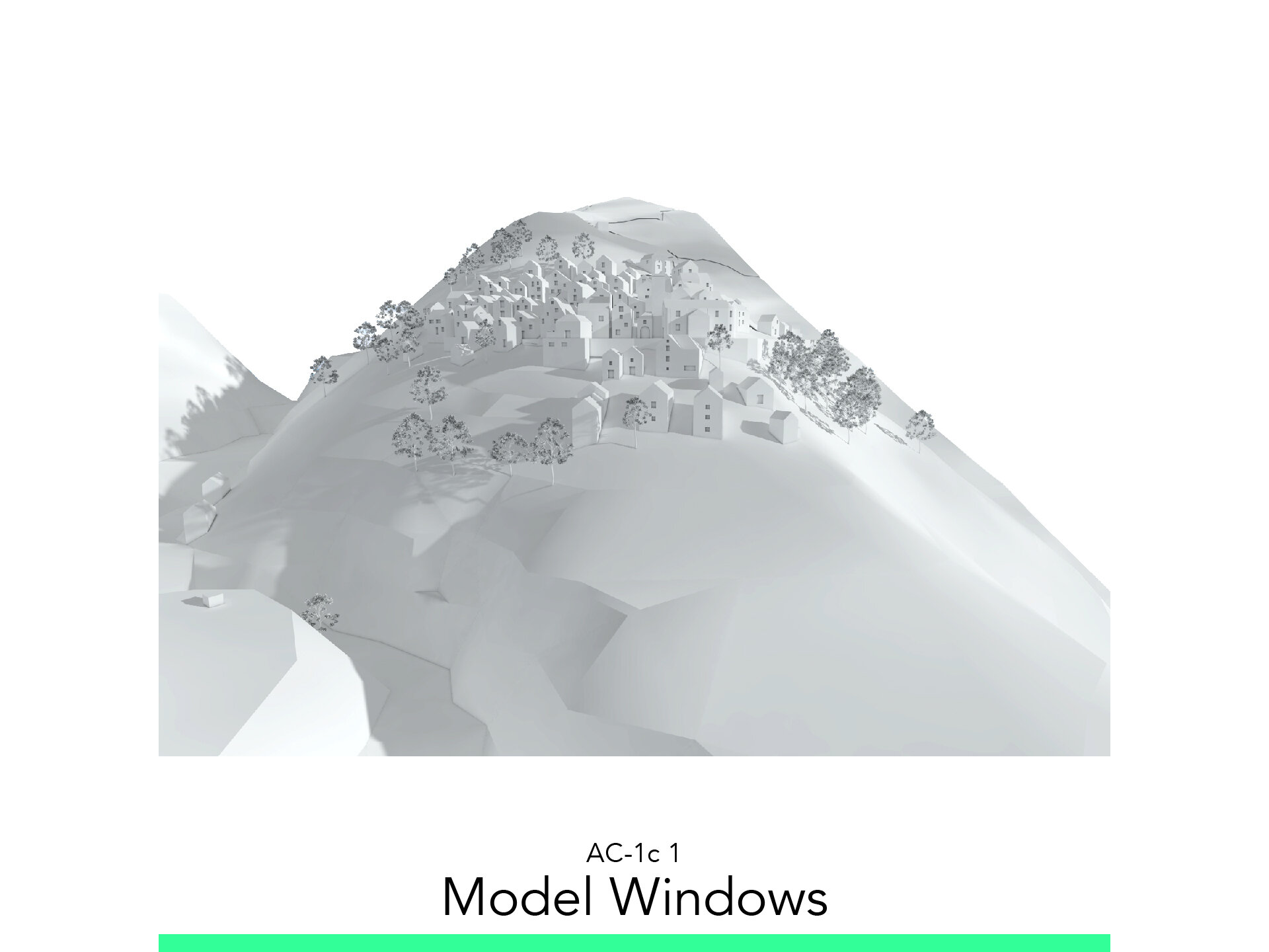
Model Windows
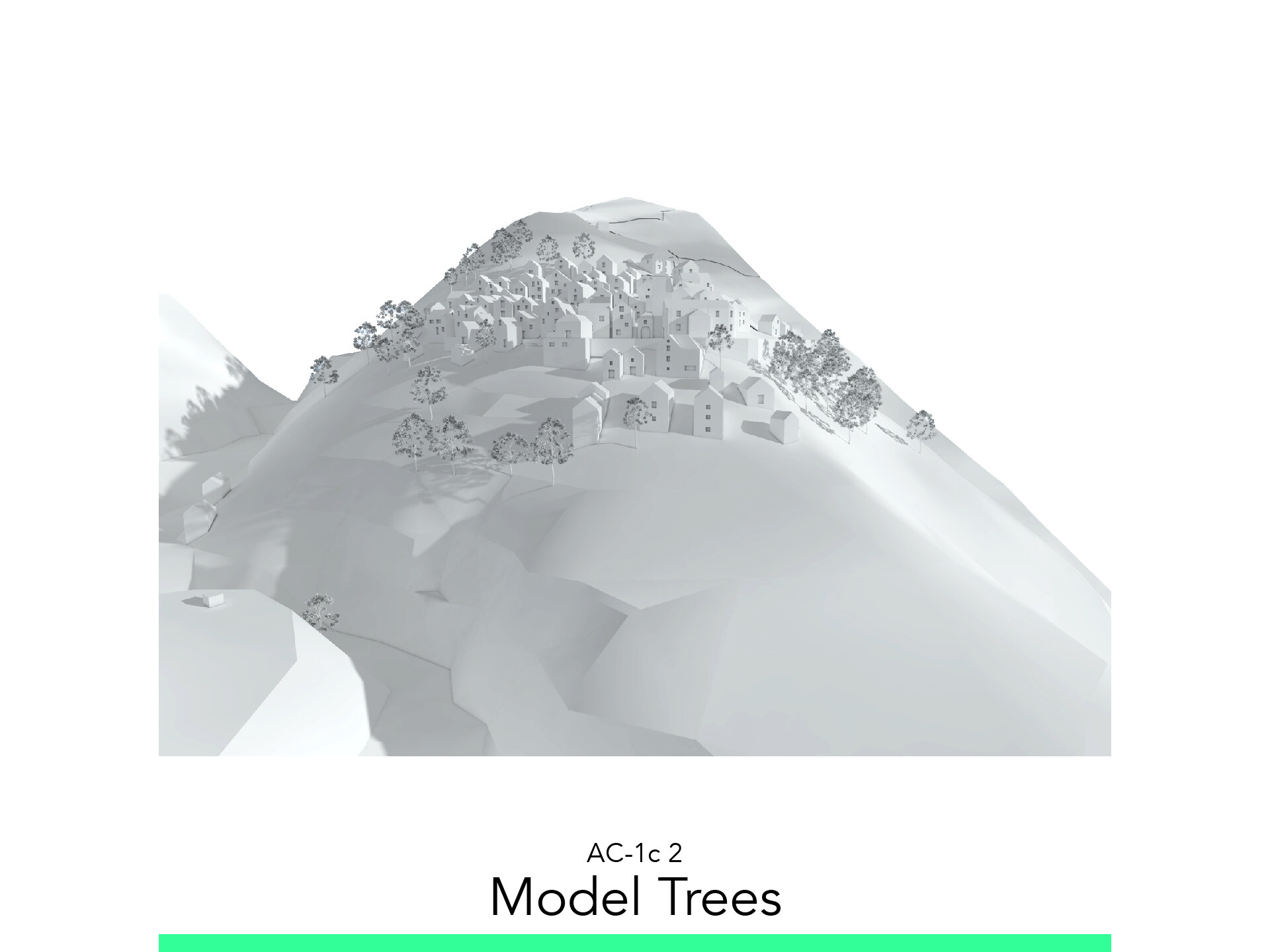
Model Trees
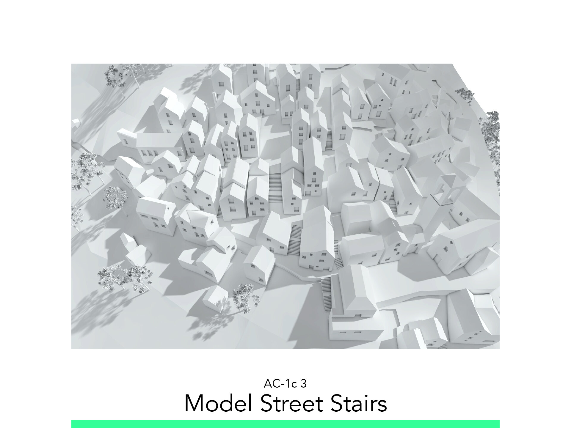
Model Street Stairs
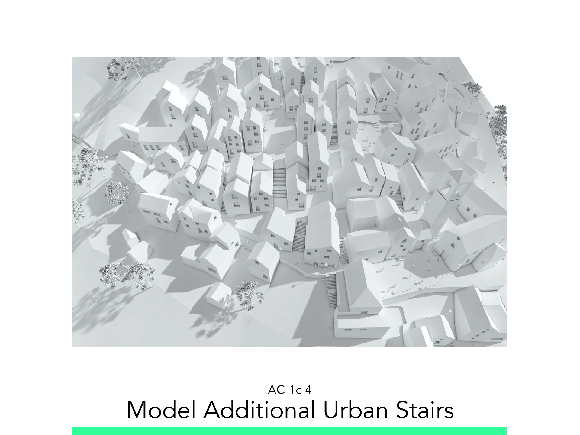
Model Additional Urban Stairs
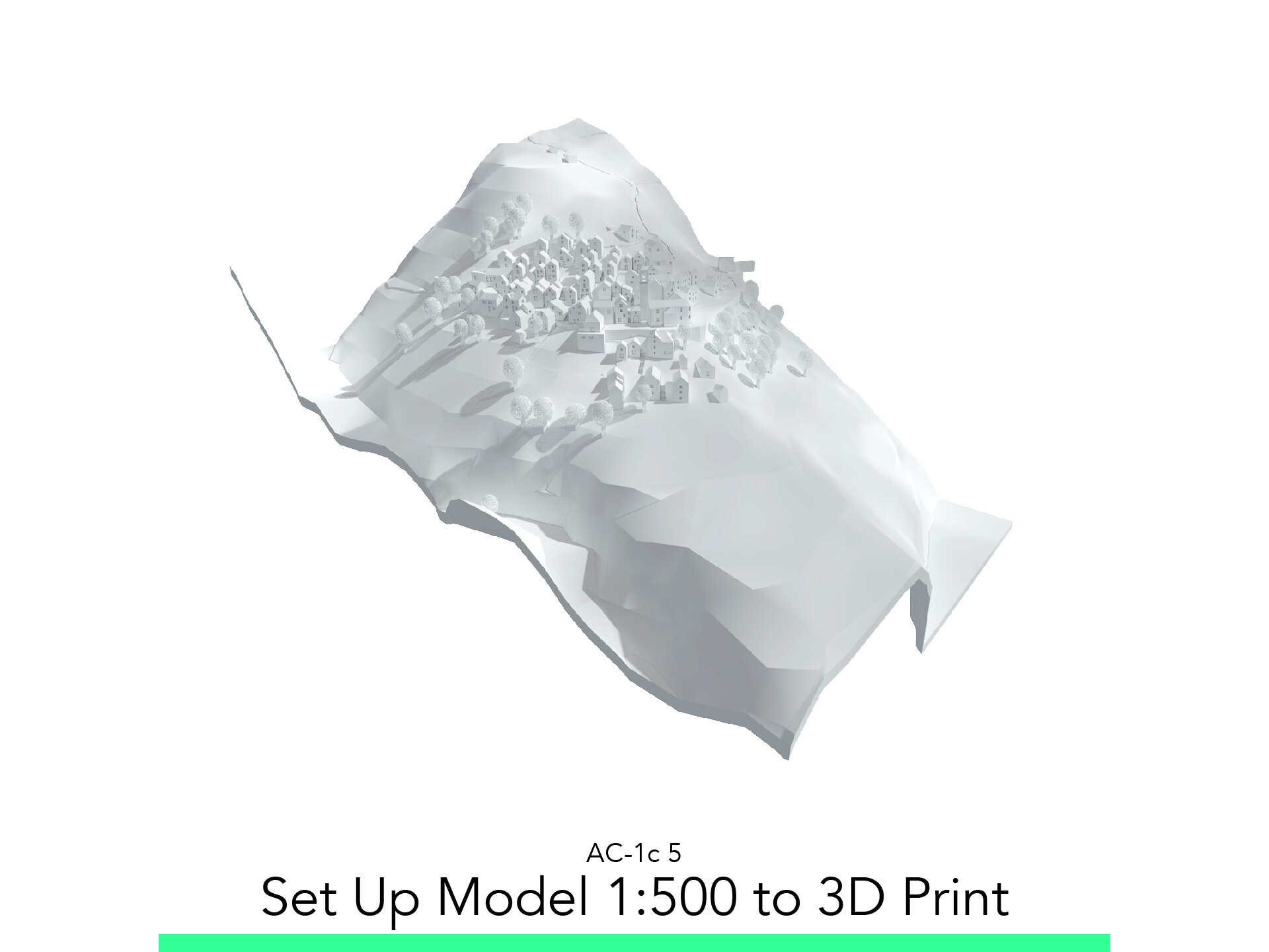
Set Up Model 1:500 to 3D Print
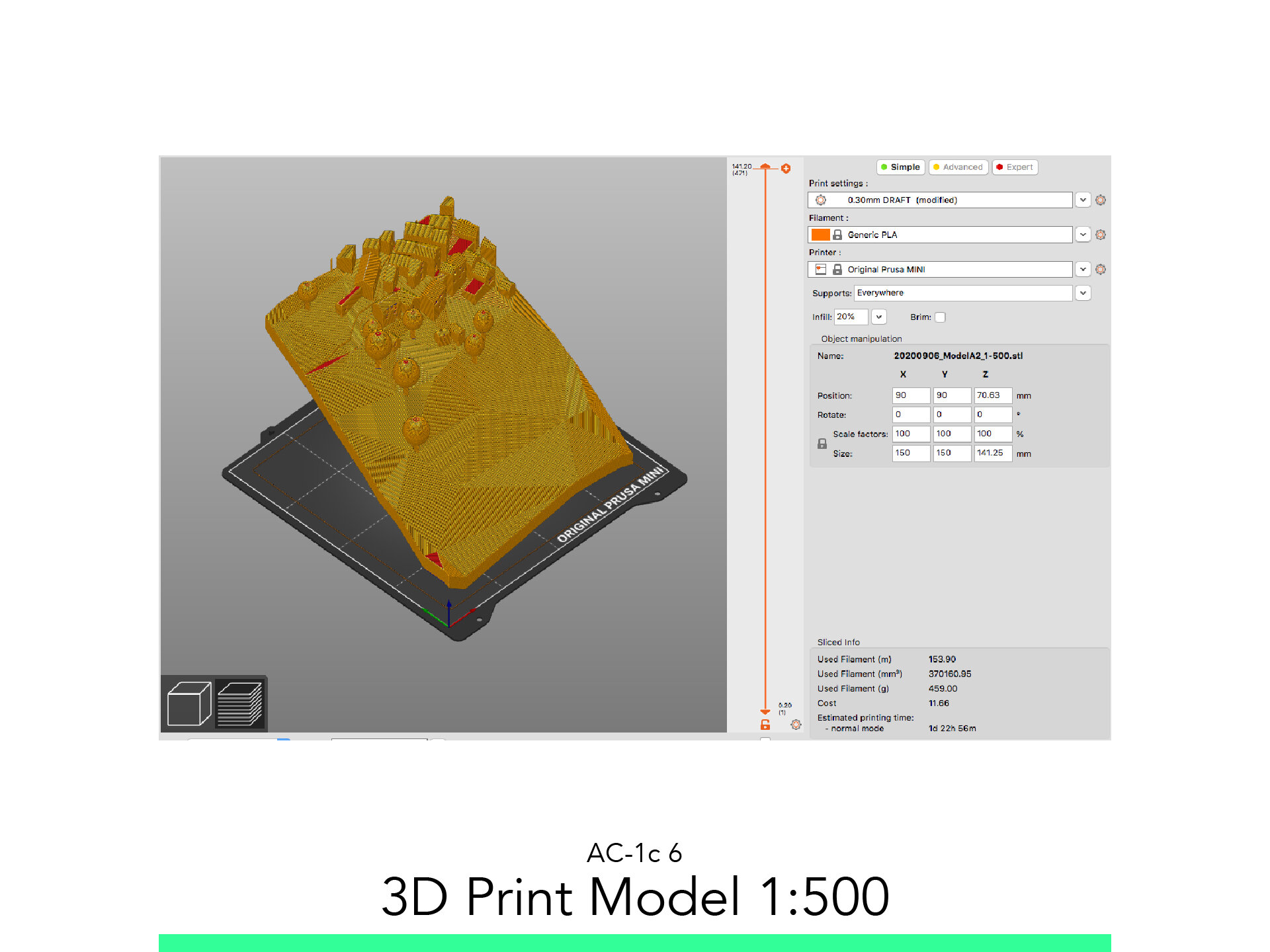
3D Print Model 1:500
The materials you will need
Your laptop with internet connection to download and Install Software during the course.
Tutorial content
• 6 Videos
• Full Tutorial Script
• Sample 3D File
Why take this tutorial
This is the final step of the process made int the courses of AC-1b and AC-1a. In the previous ones you made the basic of a context model to fully show his topography and location. But in here you will give live to all the elements and spaces, give logic to the live and construction in a really complex topographic place. From here you will have a complete context to insert your project, to compare and contemplate clearly how they relate. This is a perfect conclusion of an intermediate develop of an architecture project’s context.
1. Model Windows

1.1. Clean Model
Go to the 3D Context Mesh.
Select both meshes and change the following settings:
Structure: Box
Surface: Default
Elevate the Lower mesh to become a real Sidewalk of 10cm, by rising it 50cm.
Adjust the Plaza to intersect the buildings around it.
1.2. Morph Windows
Adjust the following Settings:
Layer: 815 Context Detail Oper
Draw a Window onto a surface.
Extrude it.
Repeat as many Times as details you wish to add to your model.
1.4. Substract Operators
Selecting all operators and set as Operator.
Select all the Buildings 103 Building Slabs and set Target.
Select the Subtraction operation.
Execute.
Turn off the Layer 815 Context Detail Oper.
2. Model Trees

2.1. Model 3D Printable Trees
Start the “Object” command and adjust the following settings:
Layer: 834 3D Print Trees.
Geometry Method: Simple
Enter the Settings window Cntrl+T
Search for Tree Model Detail or navigate the folder: ArchiCAD Library > Visualization > Site Improvement > Garden and Select Tree Model Detail and adjust the following setting:
Tree Shape: Pick a General Shape
Dimension and Trunk: Trunk Diam. 1m (for 1:500)
Crown Type: Ellipsoid
Resolution Crown: 25
Click on the Model to place it.
Select it and Adjust dimensions as wished.
2.2. Model Visual Trees
Select all Model 3D Printable Trees.
Drag a Copy to 500m upnwards.
Go to Menu: Edit/Element Setting/Edit Selection Set
Set the Layer to: 835 Visual Trees
Turn the Layer on, and the 834 Layer off.
Select the new Trees and drag them 500m Downward
Open the Setting Window while all selected and adjust the following settings:
Dimension and Trunk: Trunk Diameter 0.45m
Crown Type: Detailed
Resolution Crown: 6
3. Model Street Stairs

3.1. Measure Steps
3.2. Start Stairs
Start the Stairs from the Favorite Concrete Stairs without Finish command the adjust the following Settings:
Layer: 836 Street Stairs
Top: Not Linked
Wide Measure 0.9m (In my Case)
3.3. Model Stairs
Click on the vertices to start.
With the mouse, set the direction and amount of steps as the program visualize them for you.
Double Click to accept.
3.4. Solid Element Operation
Activate the Solid Element Operation Palette.
Select the Stair sand Set as Operator.
Select the Terrain and set as Target.
Set Operation as Subtraction with Upward Extrusion.
Execute.
4. Model Additional Urban Stairs

4.1. Street Lamps
Start the “Lamp” command and adjust the following settings:
Layer: 833 Street Lamp
Geometry Method: Simple
4.2. Street Lamps
Start the Object Command and adjust the following settings:
Open the Settings Window Ctrl+T
Enter Outdoor Bench in the search field or navigate the folders: Basic Library > Visualization > Site Improvments and select the Outdoor Bench.
Click once on the model for the center position.
Move the mouse to visualize the desired rotation.
Click to confirm placement.
4.3. Model People
Start the Object Command and adjust the following settings:
Layer: 832 People
Geometry Method: Rotated
Open the Settings Window Ctrl+T
Enter Man Hands in Pocket in the search field or navigate the folders: Basic Library > Visualisation > People and Vehicles > People and select the Man Hands in Pocket
Under Model Activate the Override Surface button and select Pain-Titanium White
Click once on the model for the center position.
Move the mouse to visualize the desired rotation.
Click to confirm placement.
Enter the Settings window Ctrl+T.
Search for Street Lamp, pick one and model it.
5. Set Up Model 1:500 to 3D Print

5.1. Set Up Pieces
From the “Site Plan” set the number of pieces and Scale
With the Morph command, draw a rectangle as big as your building plate 1:1 (0.15 x 0.15m) for Example. And assign the Layer: “803 Model Boundaries 1:500”
Scale it as many times as the model should be. (500Times for 1:500 for Example)
Start the “resize” Command
Draw a 1m line
Then input the desired Value “500”
Accept
Set amount of pieces and the exact Area you wish to print.
5.2. Set the Terrain
From the 3D Window, make sure the Layer 803 is on.
then drag a copy of one of the 803 pieces to match the lowest part of your model.
Assign it the Layer 817 Model Base 1:500.
Offset the sides to math the total size of the model.
Drag another Copy 1m Above it.
Assign it the Layer 816 Model Base Operator 500.
Offset 5m.
Extrude it as High as the highest point of the model.
Activate the Volume Operation Palette.
Select the Model Base Operator and set as Target.
Select both of the modeled Terrains as Operator.
Set the Operation to Subtraction with Downward Extrusion.
Execute.
Select the lower remaining flat morph 817 Model Base 1:500.
Extrude it as high as the highest point of the model.
Set it as Target.
Select and Set the 816 Model Base Operator 500 as Operator.
Set the operation as Subtraction with Upward Extrusion.
Execute.
Select the Lower Terrain Mesh.
Drag a Copy down 5m.
Assign it the layer “816 Model Base Operator 1:500.
Set it as Operator.
Select the Model Base 1:500 as Target.
Select the operation Subtraction with downward extrusion.
Execute.
Select All Buildings.
Set them as Target.
Select the Operator Terrain Mesh and set as Operator.
Set the Operation as Subtraction with downward extrusion.
Execute.
Turn Off the 816 Model Base Operator 1:500.
In the View Map, create a new Folder called: “Model 1:500.
Inside it, Save 3D View as 1:500 Model Full.
5.3. Apply Buildings to Terrain
Select All Buildings inside the 1:500 model and set as Operators.
Select the Model Base and set an Target.
Execute a Addition and leave only the Model Base On.
With the Live Section Tool, Cut out any buildings halfway in the model.
Redefine the View 1:500 Model Full.
6. 3D Print Model 1:500

6.1. Export STL
From the View: 1:500 Model Full turn on as Wire frame the layer 803 Model Boundaries 1:500.
Use it as reference to make a live section and leave one of the pieces visible.
Save the view as 1:500 Model A
Save it as STL
Name it with date_description_Scale format
Then flip the live section to leave the other piece of the model visible.
Save the Model as 1:500 Model B
Save that STL as well
Name it with date_description_Scale format
And so on… until all pieces have saved.
6.2. Slice STL
Run Slicer.
Drag and Drop the STL File into the Viewport.
Click on the Green “Simple button at the top left.
Adjust the following options:
Print Setting: 0.3mm DRAFT
Filament: Generic PLA
Printer: Select it
Support: Everywhere
Infill: 20%
Click on Slice Now.
Preview the First Layer.
On the lower left corner of the App, click on the Layered Icon to get to the Preview Window.
Use the slider to simulate the print and control that all pieces are sitting on the buildplate.
Insert the SD Card, save the GCODE with the following Format.
Name_Date_Description_PrinterModel_PrintTime
Go Print!
Follow your study path with these recommended tutorials


Model in ArchiCAD for the absolute first time with me!
Let me teach you basic commands of the software for you to be ready work on your projects. Start from the very basics and follow me step-by-step in the process of giving more detail to your architectural model.