AC-2a Context Model - Flat


About this Tutorial
This course is intended for intermediate learners of ArchiCAD or/and interested in Modeling as subject. Self-taught users can also profit from the structure to consolidate more developed concepts. Here we have a good first steps to download 2D information and a 3D model of a good data base, learn how to insert it and organize it in ArchiCAD. Create, organize, shape and locate the buildings of the context. To finally 3D Print it so it could be available to physical experimentation.
Skill level and duration
Level: Intermediate Users
Duration: A couple of hours tops!
In this tutorial you will learn
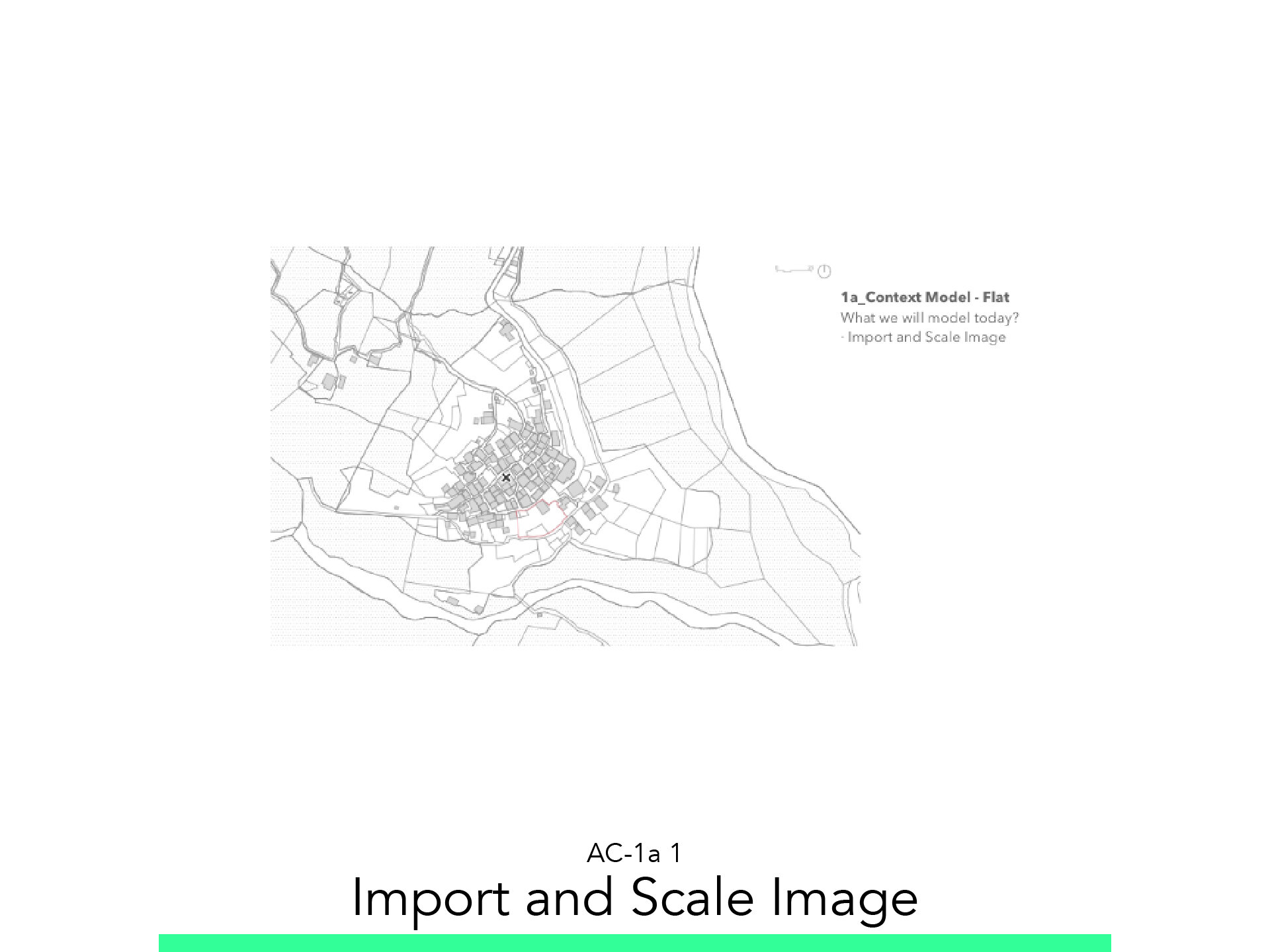
Import and Scale Image
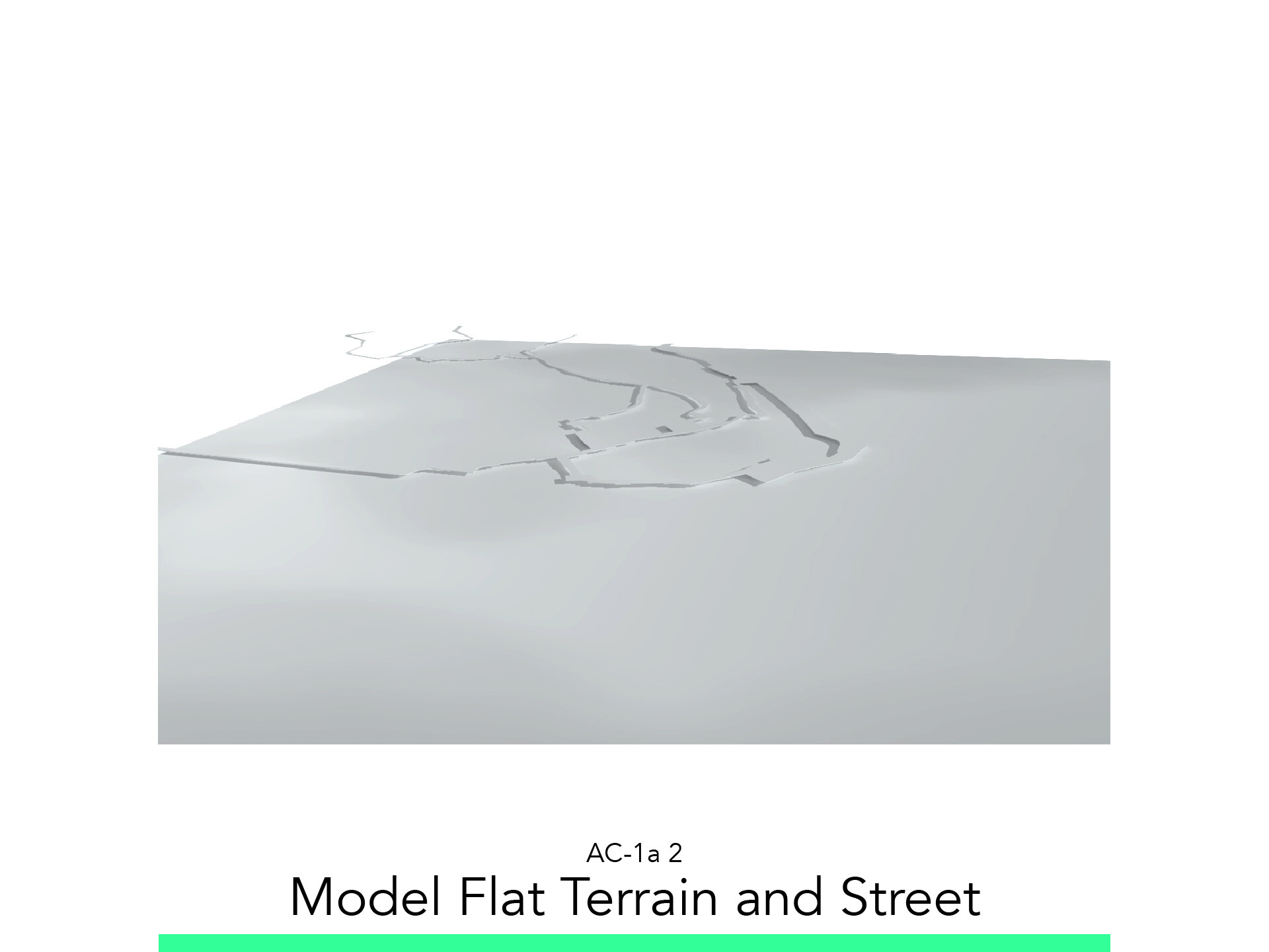
Model Flat Terrain and Street
Model Buildings
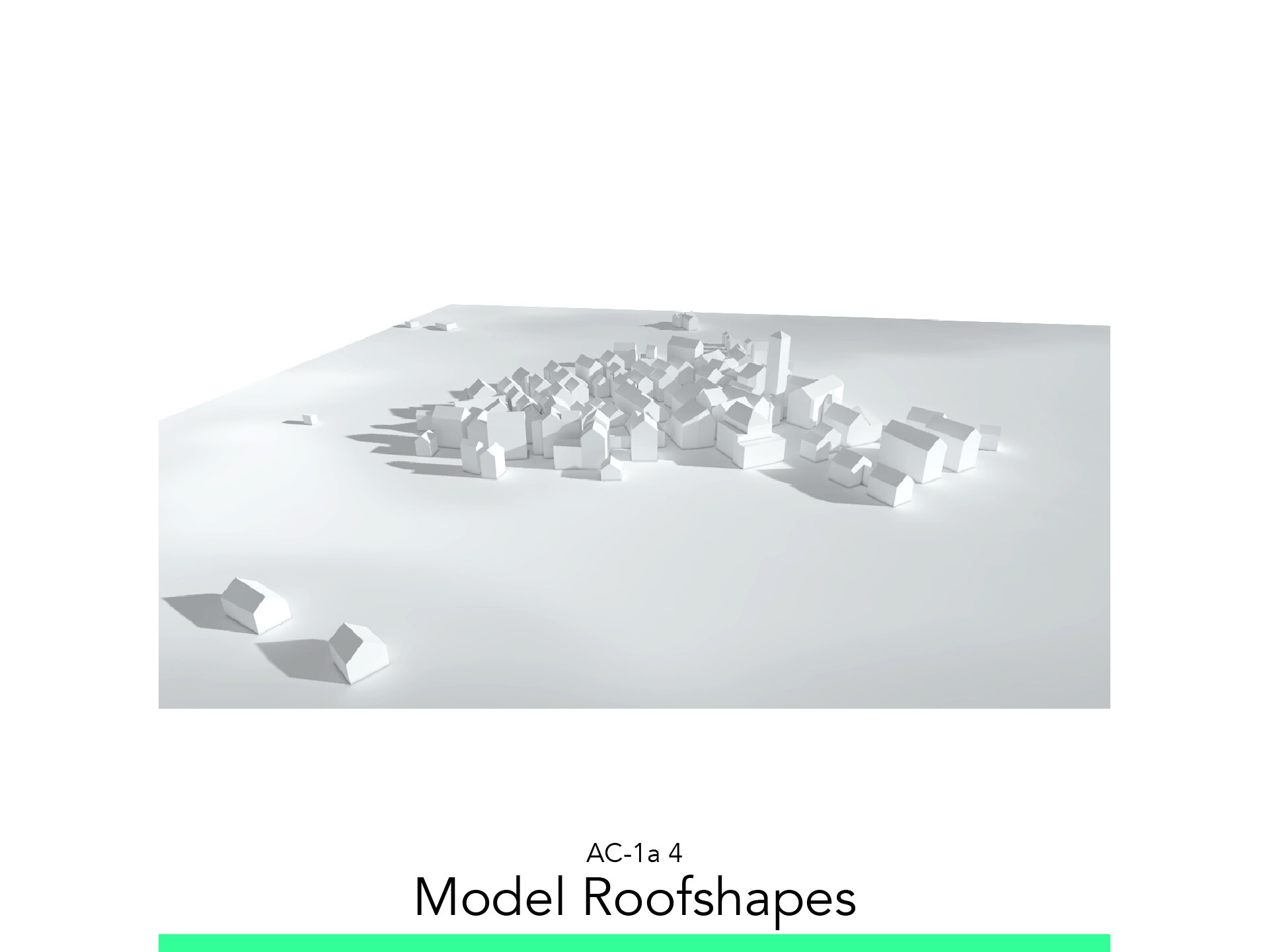
Model Roofshapes
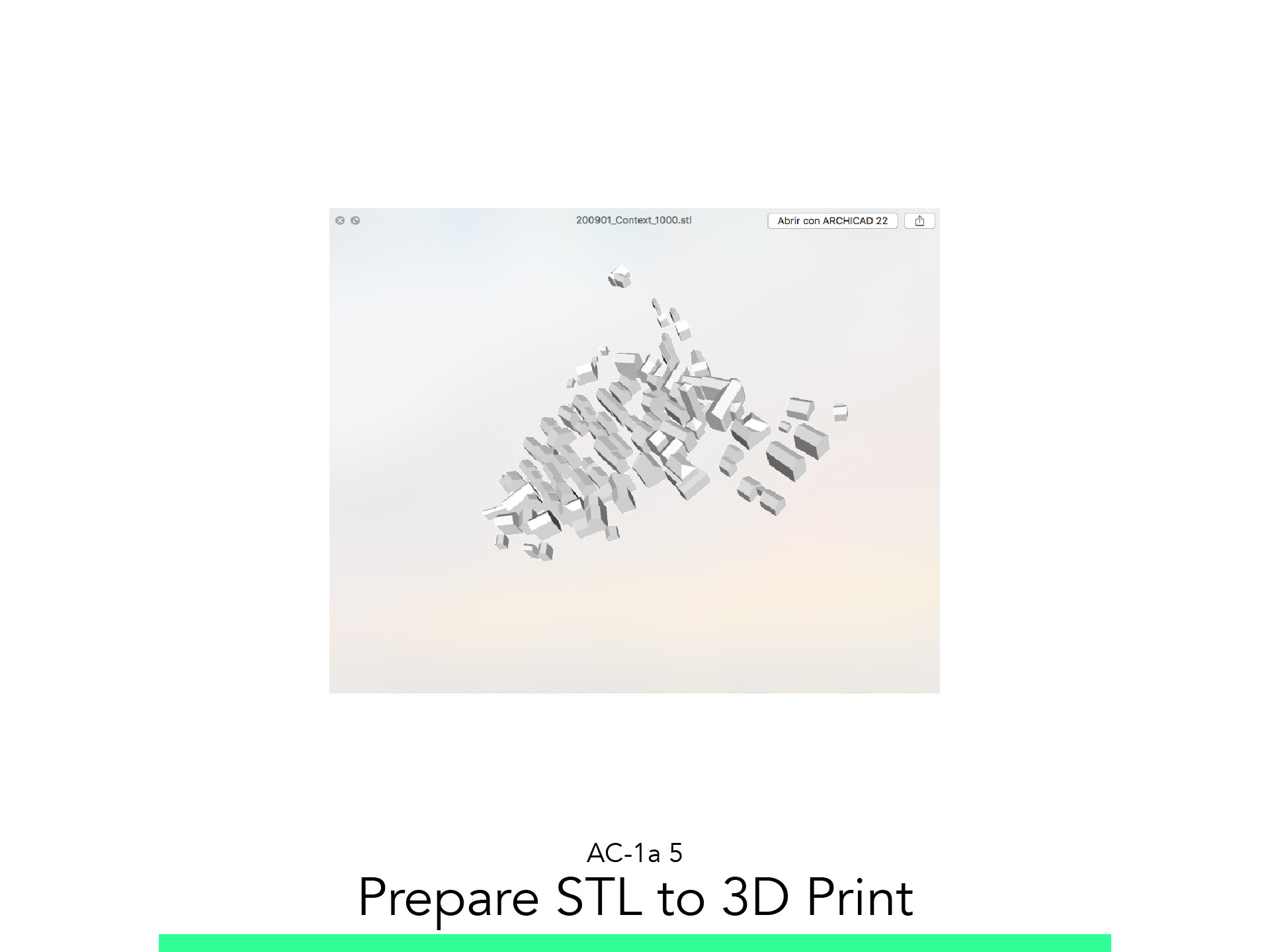
Prepare STL to 3D Print
Slice and Export the GCODE
The materials you will need
Your laptop with internet connection to download and Install Software during the course.
Tutorial content
• 6 Videos
• Full Tutorial Script
• Sample 3D File
Why take this tutorial
Here you will learn the basic steps to create a Context Model. This will be very useful in the next steps, where you will learn how to fully develop it, but this basic skills are crucial to fully understand and develop any context that you want to model for your architecture project. Its required that you already know basic skills in ArchiCAD and in 3D Printing so you can also take the next step of exporting and printing it, completing the process to fully show and work with the context of your architectural project.
1. Import and Scale Image

1.1. Create Folder
In the “View Map” create a Folder named “Context”.
1.2. Cadastral PDF
In the Project map create a new Worksheet named PDF Cadastral.
Drag and Drop the PDF File from the AC-1a_Links folder provided.
Select the image and change its Layer to 102 Reference Vector.
Using the Drag Ctrl+D and the Rotate Ctrl+E command position the image as close to the origin possible.
Start the Resize command.
Select the image.
Go to the Menu Edit / Reshape / Resize to start the Resize command or use Ctrl+K.
Click on the 0 of the graphic scale of the image.
Click on the 25 of the same graphic scale, then
Enter the value in Meter there should be between those two points. 25.
Rotate the image to make North point straight upward.
Set the Scale of the Worksheet to 1:1000.
From the View Map right cliCk on the Folder Context and select Save Current View and Leave the default name.
1.3. Satellite JPG
In the Project Map create a new Worksheet named JPG Satellite Image.
Drag and Drop the File Satelite72ppi.jpg from the provided AC-1a_Links folder.
Select the image and change its Layer to 102 Reference Image.
From the View Map right click the previously saved view W-01 PDF Cadastral and select Show as Trace reference. Nothing will happen, its normal, keep going.
On the Trace Reference Panel, activate All Kind of visible elements and set transparency to be abel to see both images.
Select the Satellite Image and using:
Drag
Resize
Match the Satellite image with the cadastral survey as much as you can
2. Model Flat Terrain and Streets

2.1. Flat Terrain
From the Project Map double click on the Ground Floor.
Change the Scale to 1:500.
Change the Pen Set to 03 Architectural 100-02.
From the View Map right click the Folder Context and select Save Current View and rename as Site Plan.
Start the Slab command and adjust the following settings:
Layer: 109 Terrain_slab
Reference Point: Top
Structure: Simple
Bottom and Top: 0.50 and 0.00
Pen Uncut: 201
Model a Square covering more than just the area of interest.
Check the Result in 3D by double clicking the Generic Perspective from the Project Map.
2.2. Street Slab
Start the Slab command and adjust the following settings:
Layer: 105 Streets
Reference Point: Top
Structure: Simple
Bottom and Top: 0.15 and 0.00
Pen Uncut: 201
Model the Streets.
Check the Result in 3D and save the View as 3D Context Flat.
3. Model Buildings

3.1. Slabs
Start the Slab command and adjust the following settings:
Layer: 103 Building Slabs
Reference Point: Bottom
Structure: Simple
Bottom and Top: 5 and 0.00
Pen Uncut: 181
Cover Fill: Active
Cover Fill: Background
Cover Fill Background: Pen 19
Model the Building.
Adjust the height of the Buildings as you model.
Check the Result in 3D.
4. Model Roofshapes

4.1. Set Up Desktop
Set Up your Desktop to be able to see a reference Photo.
4.2. Create Roofs
Start the Roof command and adjust the following settings:
Layer: 104Building_roof
Geometry method: Pitched Roof
Construction Method: 3-point rectangle
Structure: Simple
Thickness: 0.01m
Model a Roof, adjust the angles and faces.
Try Taking one modeled Roof, and drag a copy of it to the next building, then reshaping it to fit.
4.3. Solid Element Operation
Go to Menu: Design / Solid Elements Operations and follow the steps
Select the Building Volume, then click on Target.
Select the Roof, then click on Operator.
Select Subtraction with Upward extrusion.
Click Execute.
4.4. Hide Layer
Turn the Layer: “104 Building Roof” off.
Redefine the View.
5. Prepare STL to 3D Print

5.1. Create Printable Square
From the View Map double click on Site Plan.
Start the Morph Command and adjust the following settings:
Layer: 803 Model Boundaries 1:500.
Draw a very small rectangle of 0.15 x 0.15m, which is the actual Build Footprint of the 3D Printer.
Select the Rectangle and Start the Resize command Ctrl+K.
Click on a Corner then enter the 1 Value.
Then enter the value 500 and confirm.
5.2. Visualize
Right Click on the Context folder in the View map and select: New Folder.
Rename as Model 1:1000.
Right click the new Folder and select: Save Current View As.
Rename it as 1:1000 Model Full.
Now multiply the Rectangle as many times as the big model requires.
5.3. Export Model
From the View Map double click on 3D context Flat.
Turn the layer 803 Model boundaries 1:500 on.
Select the Buildings you would to 3D Print.
Right Click a blank area and select Show selection in 3D.
From the Menu: File / Save As….
From the Menu: File / Save As….
Name it with date_description_Scale format.
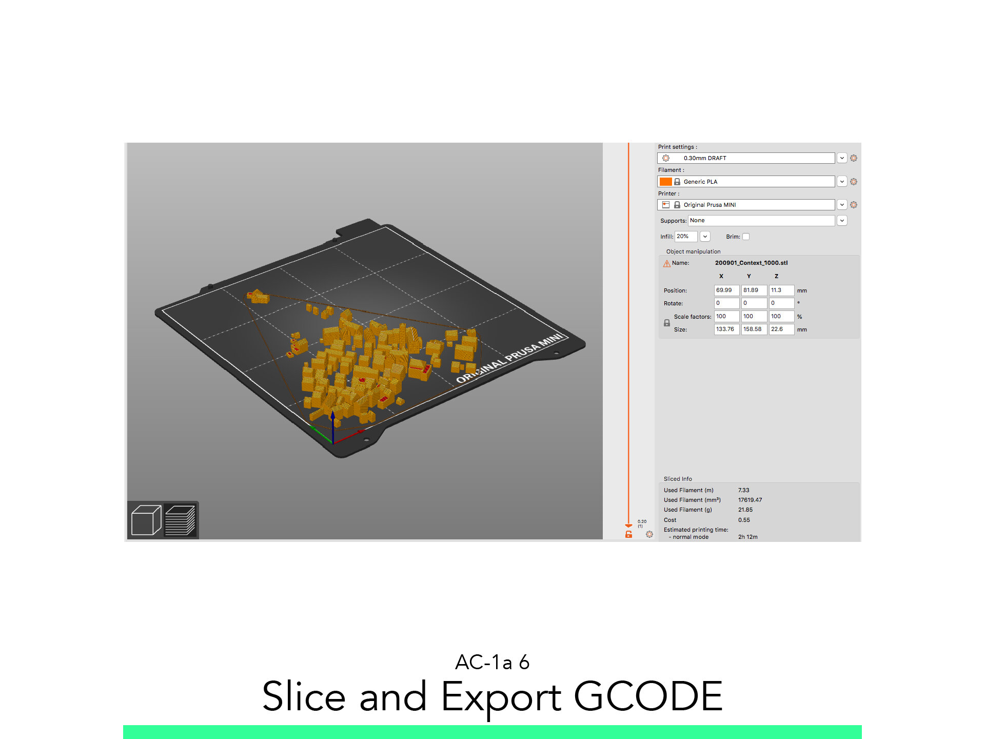
6. Slice and Export the GCODE

6.1. Adjust Model
Run Slicer.
Drag and Drop the STL File into the Viewport.
Click on the Green “Simple” button at the top Right.
Adjust the following options:
Print Setting: 0.3mm DRAFT
Filament: Generic PLA
Printer: Add your Printer Model and select it
Support: None
Infill: 20%
6.2. Slice
Click on Slice Now.
Preview the First layer.
On the lower left corner of the App, click on the Layered Icon to get to the Preview Window.
Use the slider to simulate the print and control that all pieces are sitting on the Build plate.
Insert the SD Card, save the GCODE with the following Format.
NAME_Date_Description_PrinterModell_PrintTime
Go Print!
Follow your study path with these recommended tutorials


Model in ArchiCAD for the absolute first time with me!
Let me teach you basic commands of the software for you to be ready work on your projects. Start from the very basics and follow me step-by-step in the process of giving more detail to your architectural model.