F-5 Freeform Model


About this Tutorial
This course is intended for intermediate learners of Fusion 360 and/or Modeling as a Subject. Self-taught users can also profit from the structure to consolidate more developed concepts. These are the first steps to create a Free Form Model, a model that could be edited and shaped with a sort of commands and tools. This is a interediate learning of Fusion 360.
Skill level and duration
Level: Intermediate Users
Duration: A couple of hours tops!
In this tutorial you will learn
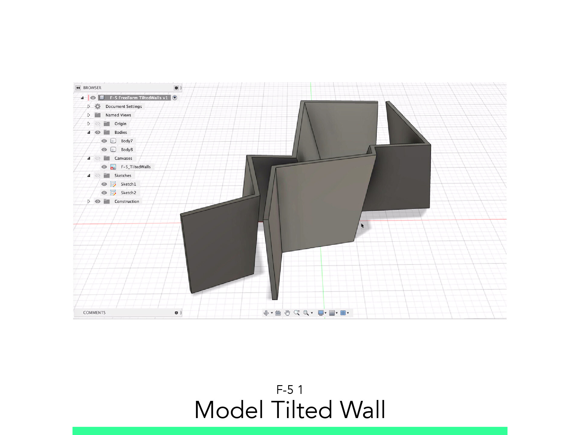
Model Tilted Wall
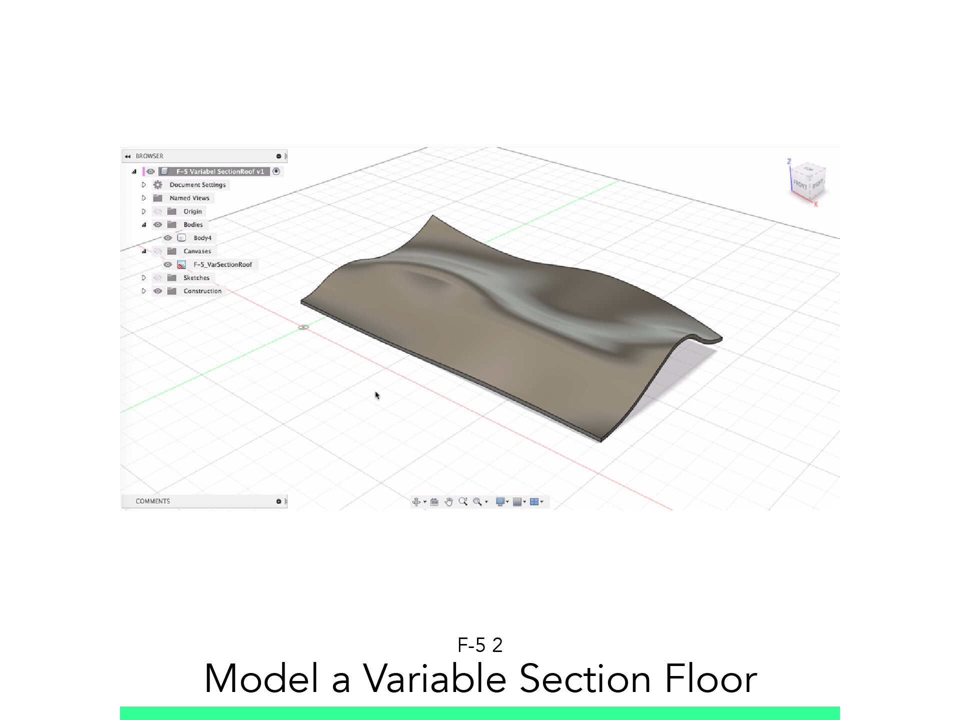
Model a Variable Section Floor
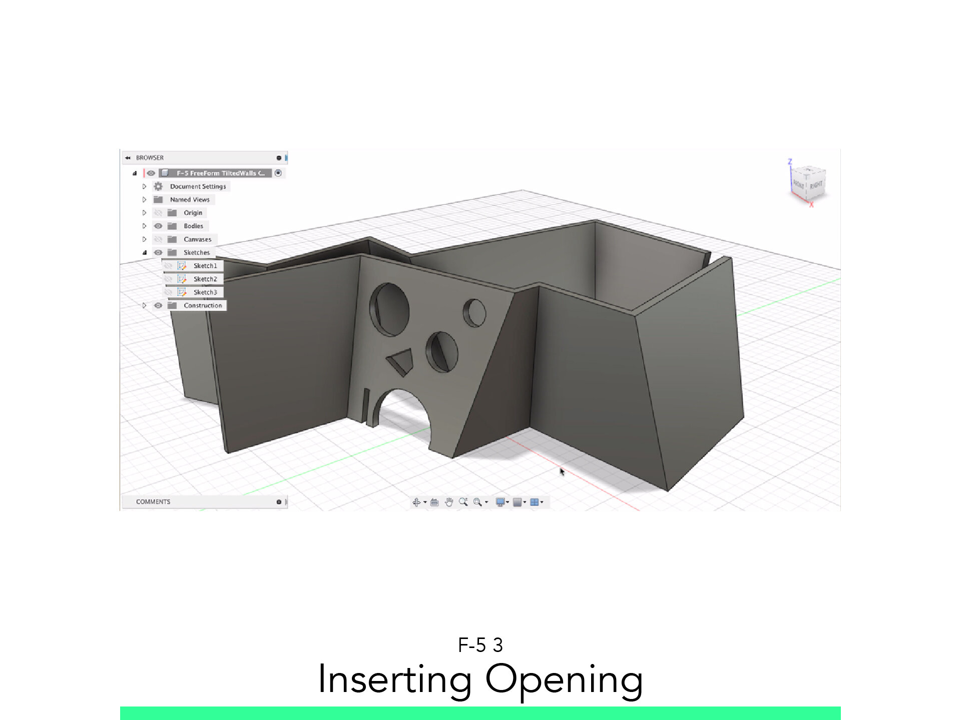
Inserting Opening
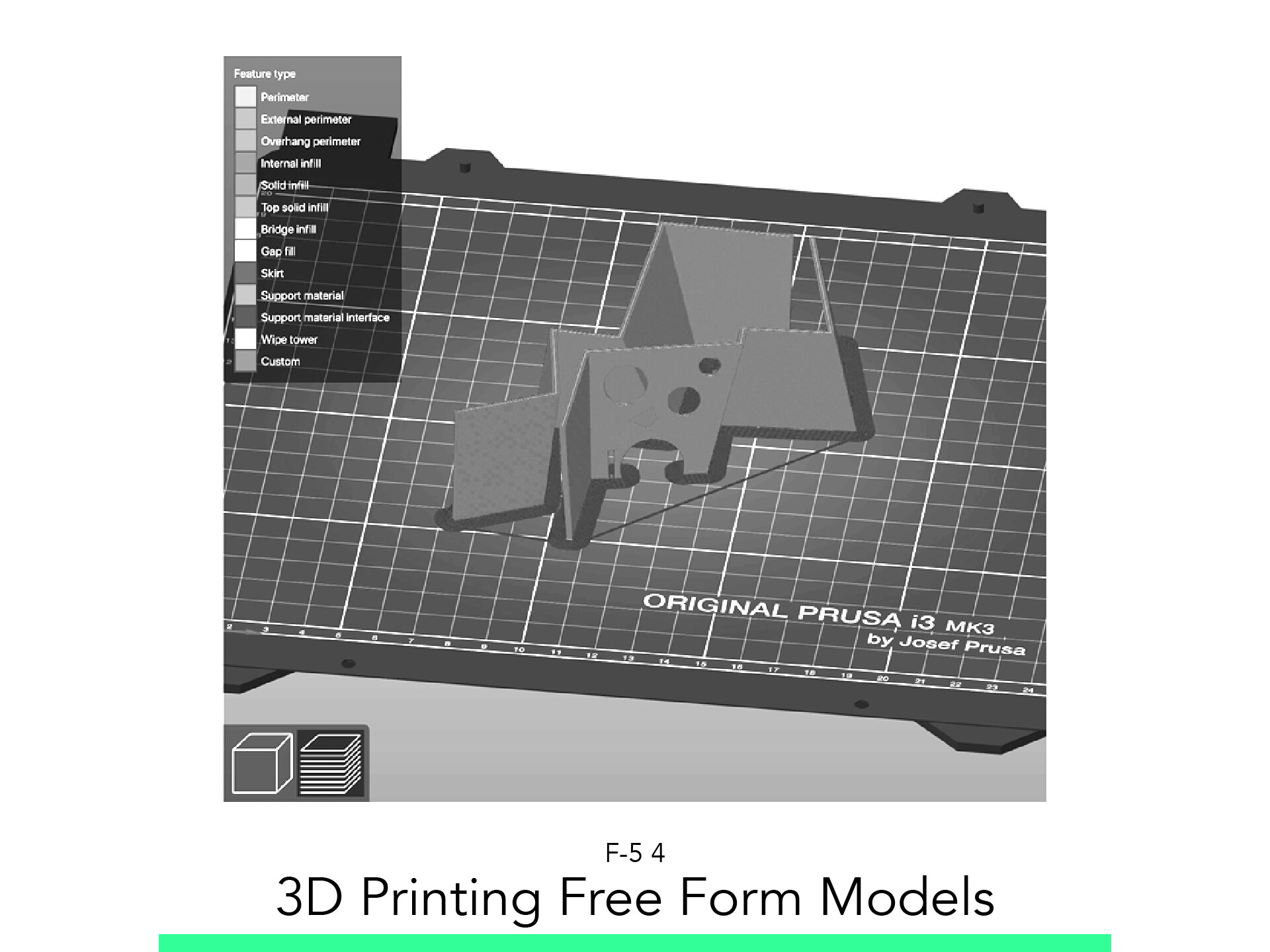
3D Printing Free Form Models
The materials you will need
Your laptop with internet connection to download and Install Software during the course.
Tutorial content
• 4 Videos
• Full Tutorial Script
• Sample 3D File
Why take this tutorial
Fusion 360 is a good Modeling program of Autodesk, where you can realize a good and clear model more freely than any other program. This skills learned here are some key points to start to create more organic and curve, shapes surfaces and volumes. These shapes are more advanced to add in an architecture project, when you are pointing to a more complex design. Here you will learn the tools to develop the volumes and finally export it in STL to 3D Print it. Fully learn to use Fusion 360.
1. Model Tilted Walls

1.1. Import and Scale Sketch
Sketch the bottom part of the walls.
Run the line command.
Rune the Offset command.
Close poligons.
Select all lines.
Right Click and select “copy”.
Finish the sketch.
1.2. Offset a Plane
Set the height.
1.3. Start a New Sketch
Select the newly created plane.
Right click and select “Paste”.
Move the sketch to match the other one.
Offset the individual edges.
Move from to the “Surface” tab.
1.4. Loft
Start the Loft Command.
Activate Chaining.
Select both of the sketches.
Accept.
1.4. Patch
Start the Patch command.
Select the top of the walls.
Accept.
Repeat the Patch command.
Select the other side of the Wall.
Accept.
1.5. Stitch
Start the Stitch command.
Select all Meshes.
Make sure there are no Red lines.
Accept.
Check that the Solid has a grey icon.
2. Model a Variable Section Floor

2.1. Import and Scale Sketch
Place it on a vertical plane.
Sketch one of the contours.
Close polygons.
Finish the sketch.
Repeat until all contours are sketched.
2.2. Loft
Move from to the Surface tab.
Start the Loft Command.
Activate Chaining.
Select all of the sketches.
Accept.
2.3. Patch
Start the Patch command.
Select the top of the walls.
Accept.
Repeat the Patch command.
Select the other side of the Wall.
Accept.
2.4. Stitch
Start the Stitch command.
Select all meshes.
Make sure there are no Red lines.
Accept.
Check that the Solid has a grey icon.
3. Inserting Opening

3.1. Opening based on Volumes
Model a Solid the shape you wish to subtract.
Start the Combine Command.
Set the Operation to Subtract.
Select the Tool.
Execute.
3.2. Opening based on Sketches
Start a Sketch.
Pick the face you wish to open as surface.
Sketch the shape of the opening.
Finish the sketch.
Select the sketched surface.
Start the Extrude command.
4. 3D Printing Free Form Models

4.1. Export as STL
From the “Tools” Tab select 3D Print.
Select the solids you would like to 3D Print.
Uncheck “Send to Print Utility”.
Click Ok.
Set the Folder to Save your STL File.
Use the Following format:
date_description_Scale
4.1. Slice
Run “Slicer”.
Drag and Drop the STL File into the Viewport.
Click on the Green Simple button at the top left.
Adjust the following options:
Print Setting: 0.3mm DRAFT
Filament: Generic PLA
Printer: Add your Printer Model and select it.
Support: Everywhere
Infill: 20%
Click on Slice Now.
Preview the First layer.
On the lower left corner of the App, click on the Layered Icon to get to the Preview Window.
Use the slider to simulate the print and control that all pieces are sitting on the buildplate.
Insert the SD Card, save the GCode with the following Format.
NAME_Date_Description_PrinterModell_PrintTime
Go Print!
Follow your study path with these recommended tutorials


Model in ArchiCAD for the absolute first time with me!
Let me teach you basic commands of the software for you to be ready work on your projects. Start from the very basics and follow me step-by-step in the process of giving more detail to your architectural model.