AC-2e Model Urban Iterations


About this Tutorial
This course is intended for intermediate learners of ArchiCAD and/or interested in Modeling as a subject. Self-taught users can also profit from the structure to consolidate more developed concepts. In this tutorial you will insert your iterations of the architectural project that you have fully develop in the exercise AC-2a. Here you will insert your 2D drawings, place it in the correct spot and then modeling till you are satisfied of the idea. Then you can print it in 3D to fully see and locate it in you already printed context that you made in the AC-1b. Its a really good exercise to conclude the learning and start the proposing.
Skill level and duration
Level: Intermediate Users
Duration: A couple of hours tops!
In this tutorial you will learn
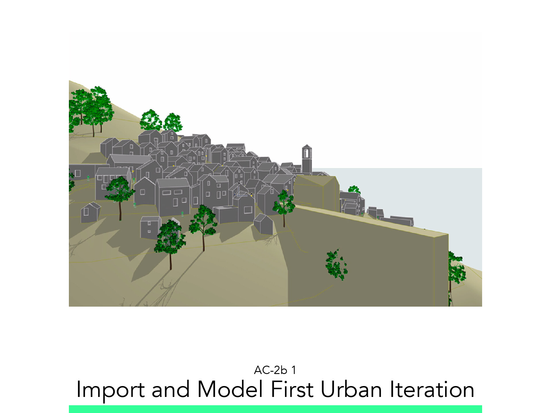
Import and Model First Urban Iteration
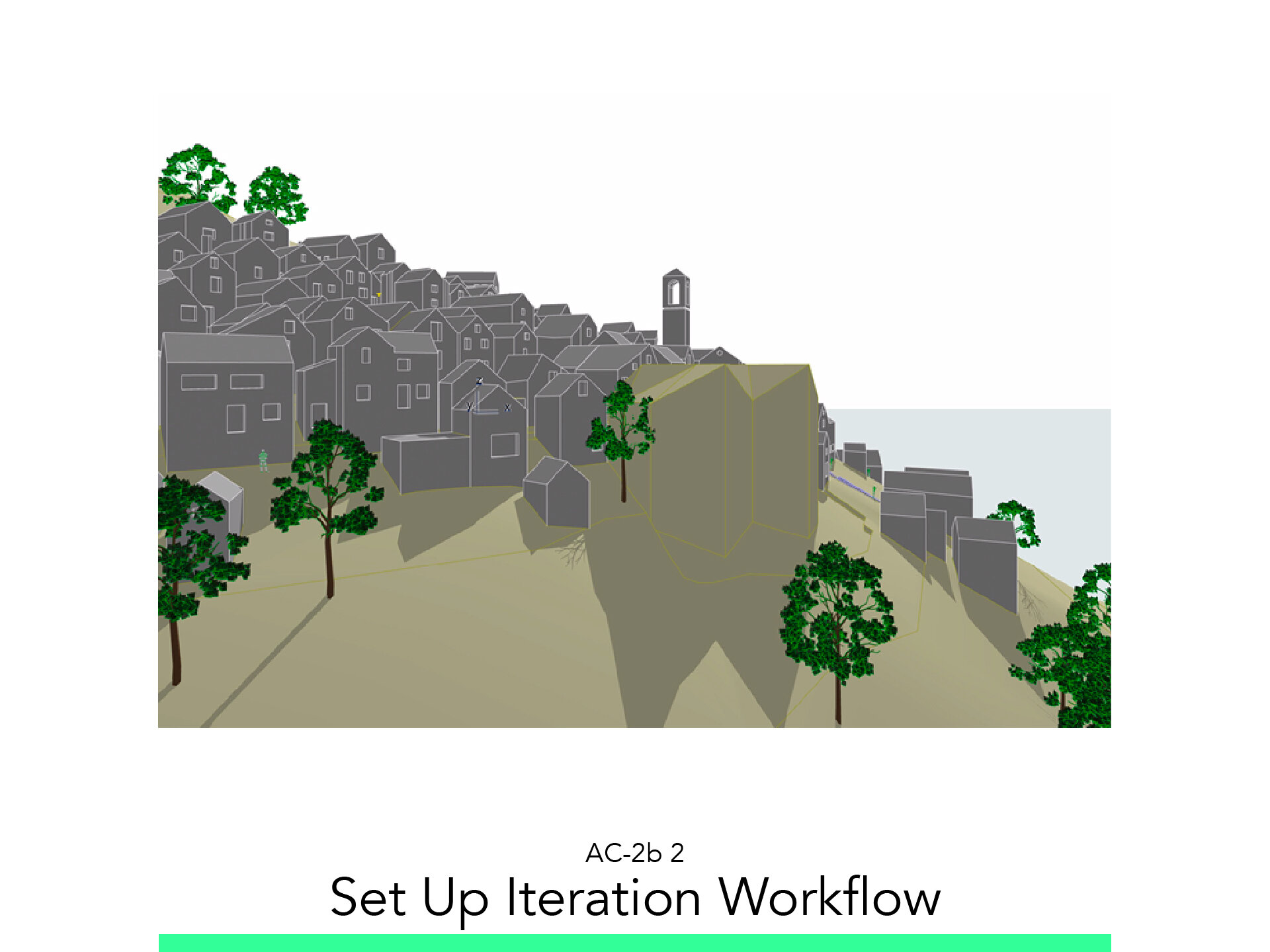
Set Up Iteration Workflow
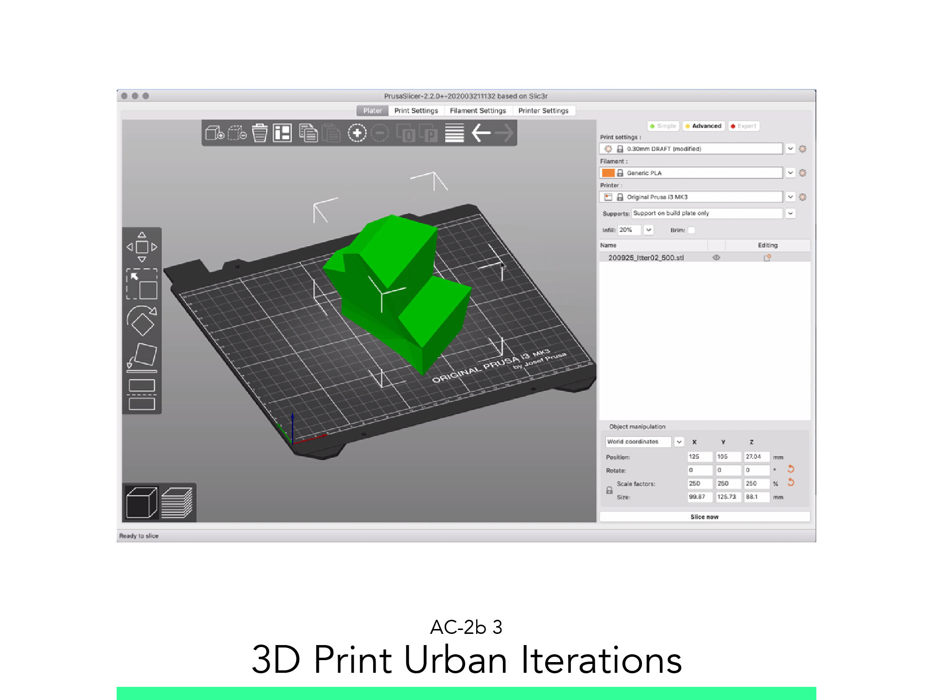
3D Print Urban Iteration
The materials you will need
Your laptop with internet connection to download and Install Software during the course.
Tutorial content
• 3 Videos
• Full Tutorial Script
• Sample 3D File
Why take this tutorial
This tutorial is an excellent conclusion of your work, taking a model you already made, fully knowing how to manage a lot of tools in ArchiCAD, to then create in it the different ideas that you have for a project. You are going to fully use the program not only to model already existing things, but also to create, to work as an architect, to compare the different options in the context, to finally print it and present it to your clients, so they can compare in a clean and clear 3D printed model. A complete and practical use of ArchiCAD for architects!
1. Import and Model First Urban Iteration

1.1. Import and Scale Sketch
Create a Worksheet:
Import JPEG.
Scale it.
Save the View.
1.2. Model First Iteration
From the View Map.
Double click on: SB500 – Context 500.
Make sure the Layer: 211 Urban Variant is on.
Save the Layer Combination as: SB500-Urban 01.
Right Click the Root folder and select:
Create New Folder
Name it: Urban Iteration 01
Right Click the Worksheet Var1.
Select Show as Trace Reference.
Make sure the Filter “Show All” is activated.
Adjust Transparencies.
Start the Morph Command and adjust the following settings:
Layer: 211 Urban Iteration
Geometry: Polygon.
Trace the contours of your Sketch
Save the View by:
From the View Map.
Right click the Folder Iteration 01 and select: Save Current View…
Name it Var01 – Context 500
Extrude the Sketch
From the View Map:
Go to SB500 – Outer Persp 01.
Change the Layer combination to: SB500-Urban 01.
Extrude the Sketch.
Save the View as: Var 211 – Outer Persp 01.
1.3. Subtract Terrain
Activating the Solid Volume Operation Panel
Set the Proposal as Target, and the terrain as Operator.
Execute an Subtraction with Downward Extrusion.
2. Set up Iteration Workflow

2.1. Configure Layer
Click on the Layer Combination: “SB500 – Urban01.
Create a new Layer Called: 212 Urban iteration.
Turn off the layer: 211 Urban Iteration.
Create a new Layer combination called: SB500-Urban01.
Model second Iteration by repeating the steps of the First but using the Layer: 212 Urban Iteration.
3. 3D Print the Urban Iterations

3.1. Export STL
From the saved view: 1:500 Model Full.
Change the layer combination to: SB500-Urban01.
Select the Proposal
Turn all other layers Off
Save the view inside its folder as V211-Model.
Save as Stereolithography
Name it with date_description_Scale format.
Change the Layer settings to only see the layer 212.
Save the view inside its folder as V212-Model.
Save as Stereolithography
Name it with date_description_Scale format
3.2. Slice the Urban Iterations
Run Slicer.
Drag and Drop the STL File into the Viewport.
Click on the Green Simple button at the top left.
Adjust the following options:
Print Setting: 0.3mm DRAFT
Filament: Generic PLA
Printer: Select it
Support: Everywhere
Infill: 20%
Click on Slice Now
Preview the First Layer
On the lower left corner of the App, click on the Layered Icon to get to the Preview Window.
Use the slider to simulate the print and control that all pieces are sitting on the build plate.
Insert the SD Card, save the GCode with the following Format
NAME_Date_Description_PrinterModel_PrintTime
Go Print!
* Import Free Shapes as STL
Import STL from Course F-5.
Set up layout.
Follow your study path with these recommended tutorials


Model in ArchiCAD for the absolute first time with me!
Let me teach you basic commands of the software for you to be ready work on your projects. Start from the very basics and follow me step-by-step in the process of giving more detail to your architectural model.