AC-1e Documentation from 3D Model Basics


About this Tutorial
This course is intended for first time ArchiCAD users. Self-taught users can also profit from these structures to consolidate essential concepts. There is a lot of material to understand in the topic of the 3D Based Documentation of an Architectural Project. In this chapter we are going to use our model to develop plans, sections, elevations, and site plans using tools to help us understand the most important elements of the BIM program. We will also include the basics we learnt about Line Weight and Modeling so we can reach an intermediate level.
Skill level and duration
Level: First Time Users
Duration: A couple of hours
In this tutorial you will learn
Overview
Context Model
Simple Solid
Interior Spaces
Inner Walls and Stairs
Inner Objects
Facade Details
The materials you will need
Your laptop with internet connection to download and install software during the course.
Tutorial content
• 7 Videos
• Full Tutorial Script
• One Single File with all the Exercises.
Why take this tutorial
This tutorial is an excellent introduction to the BIM affordances found in ArchiCAD. You will understand how to take a single developed model and extract all the drawings you require from it. You will consolidate your knowledge of how ArchiCAD works and further develop its productivity for architecture. You will also learn to integrate basic concepts learned before about CADing and modeling and you will start to understand the big universe of BIM programs. Finally, you will use a practical program to manage your time and capacities to create and develop an architecture project.
1. Overview

You must always balance time spent with power of representation. To do this it recommended to think about your design in different levels of detail, each being a coherent step after which you get a usable model with the relevant detailing for the phase you are in.
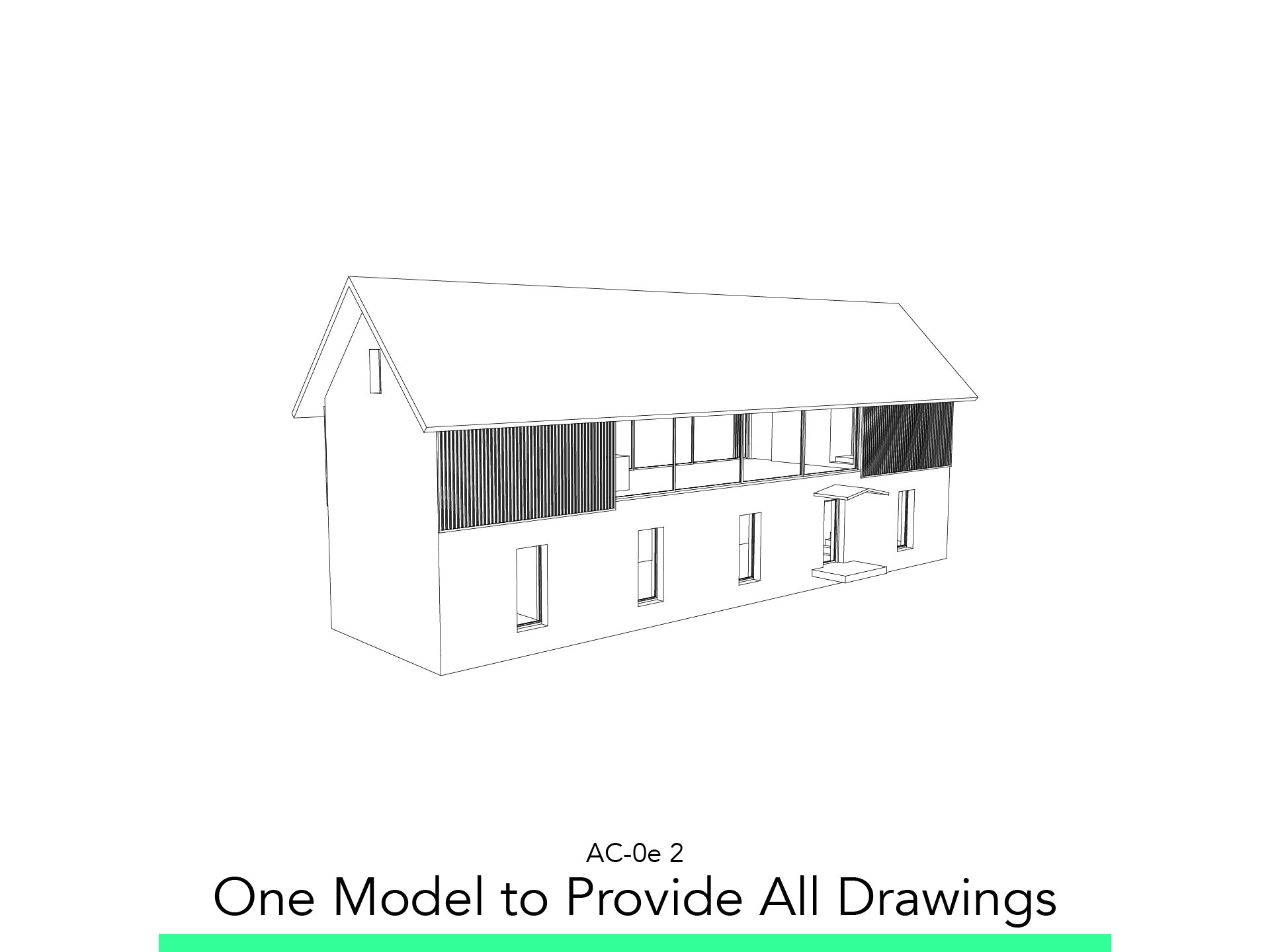
2. Develop One Model to Provide All Drawings

2.1. Walls
Add some walls that divide interior spaces, such as bathrooms and rooms.
Start the Walls Tool, Adjust the following settings and edit the already made Walls:
Wall Thickness: 0,17
Height: To Next Story
Cut Line Pen: Pen 47 (initial)
Uncut Line Pen: Pen 87 (initial)
Material: ST-00 Generic Structural
Layer: 202 Walls
Don’t Forget to use Solid Element Operation to adapt the walls with the roof.
2.2. Slabs and Stairs
The closed spaces in the 1. Story are two steps higher than the social part, so we have to separate the slab created.
Verify the following settings on the slabs you have created.
Slab Thickness: 0,45
Floor Plan Display: Home Story Only
Cut Line Pen: Pen 49
Uncut Line Pen: Pen 89
Material: ST-00 Generic Structural
Layer: 201 Slabs
The Slabs of the closed spaces should be settled 0,30 high from the Reference Plane Offset to Home Story
Create the second stair with a Slab. Start the Slab Settings, Adjust the following settings or edit the already made Walls:
Slab Thickness: 0,15
Floor Plan Display: Home Story Only
Cut Line Pen: Pen 49
Uncut Line Pen: Pen 89
Material: ST-00 Generic Structural
Layer: 201 Slabs
The Slabs of the closed spaces should be settled 0,15 high from the Reference Plane Offset to Home Story
Model or Check the Stairs in the 1. Story
Select the Stair.
Go in the Stair Settings > Layouts – Floor Plan Display: Home Story & One Story Up
Add a White Cover Fill to the 1. Story Slabs to cover the Stairs
Maybe it will appear all the stair, send it back in view with Right Click > Display Order
2.3. Windows
To create a more elaborate Window click on the already made open window of the Ground Floor.
Start the Window Settings, search on the Library for 1.3 Windows > Basic Window > Window 22.
Adjust the following settings or edit the already made Windows
Width: 1,00
Height: 2,00
Sill: 0,15
Wall Opening > Reveal: 0,24
Go to Basic Window Settings > Wall Opening > Reveal > Reveal
Select the Little Windows of the 1. Story and do the same as before
Start the Window Settings, search on the Library for 1.3 Windows > Basic Window > Window 22
Adjust the following settings or edit the already made Windows:
Width: 0,50
Height: 1,00
Sill: 2,70
Wall Opening > Reveal: 0,24
Flip with the frame inside
Go to Basic Window Settings > Reveal > Reveal Type > Reveal
2.4. Doors
To create a more elaborate Door click on the already made open window of the Ground Floor. If you already modeled check these settings, if not do remodel.
Start the Door Settings, search on the Library for 1.2 Doors > Hinged Doors > Door 22.
Entrance Door: Adjust the following settings or edit the already made Doors:
Width: 1,00
Height: 2,00
Sill: 0,15
Wall Opening > Reveal: 0,20
Flip with the frame inside
Fixture and Fittings > Casing > Outside & Inside Unchecked
Door Leaf Type > Frame Width > 0,05 x 0,05 x 0,05
Story Big Sliding Doors: Start the Door Settings, search on the Library for 1.2 Doors > Sliding Doors 22 > Sliding Door 22.
Adjust the following settings edit the already made Doors:
Inner Doors: Start the Door Settings, search on the Library for 1.2 Doors > Hinged Doors 22 > Door 22.
Adjust the following settings or edit if already placed:
Width: 0,80
Height: 2,00 (GF 2,40)
Sill: 0,30 *(GF 0,00)
Door Settings > Door Leaf > Style 1
Frame and Leaf > 0,05
Fixtures and Fittings > Casing > Outside & Inside Unchecked
2.5. Roof Display and Hybrid Floorplan
We are going to set the roof projection in 2D, as hybrid
First lets draw the polyline with these settings:
Pen: 92
Line Type: Dashed
Now lets configure the roof to not be shown in the 1. Story.
Show on Stories: Home Story Only
Don’t forget we have two roofs
2.6. Objects
Story: Start the Object Tool Settings, adjust the following Settings and model
Start the Object Tool > 1.1 Furnishing 22 > Appliances > Cooktop Built-in 22
Adjust Tap and Sink Styles
Size: 0,59 x 0,43
Geometry Method: Rotated
Start the Object Tool > 1.6 Mechanical 22 > Plumbing Fixtures > Sinks > Sink Belfast 22
Adjust Tap and Sink Styles
Size: 0,59 x 0,53 x 0,12
Geometry Method: Rotated
Start the Object Tool > 1.6 Mechanical 22 > Plumbing Fixtures > WC, Bidets, Urinals 22 > WC 22
Adjust Tap and Sink Styles
Geometry Method: Rotated
Start the Object Tool > 1.6 Mechanical 22 > Plumbing Fixtures > Basins 22 > Basin 22
Adjust Tap and Sink Styles
Geometry Method: Rotated
Draw as 2D the Shower
Pen: 75
Lets Add the walls that surround the shower Thickness: 0,17
Height: 2.00
Ground Floor: Start the Object Tool Settings, adjust the following Settings and model
Start the Object Tool > 1.6 Mechanical 22 > Plumbing Fixtures > WC, Bidets, Urinals 22 > WC 22
Adjust Tap and Sink Styles
Geometry Method: Rotated
Start the Object Tool > 1.6 Mechanical 22 > Plumbing Fixtures > Basins 22 > Basin 22
Adjust Tap and Sink Styles
Geometry Method: Rotated
Draw as 2D the shower
Pen: 75
3. Views for Modeling, Views for Printing

3.1. Overview
The Pen Set is the group of pens that you are going to use and assign to different objects and figures, ArchiCAD has already set a Pen Set to its objects and figures, you can see that it has different pens to structural elements that are cut, to the ones are projected, to non structural. We can see that this is fundamental to the expression of a plan and the way to understand it.
The Graphic Override works as a Graphic modifier of the plan you are drawing, useful for give or take out information that its not required. You can check it in the lower bar, in this file there is a Graphic Override active, you can set to “No Overrides” and see the difference.
The Model View Options it’s the configuration of how its going to be shown construction elements as Doors, Windows, Columns, Beams, Stairs and more. This with the objective of what needs to be shown in different types of plans, like architectural, structural, electric, finishes and others.
3.2. Pen Set
To Open Configuration go to Document > Pens Sets > Pens & Color (Model Views)…
Or click on the Icon on the lower bar of the screen.
Here you can see our B06 Architectural 100 that is our Pen Set for plans of 1:100 scale. Compare it with the 03 Architectural 100 of ArchiCAD and you can see how we use mostly black and grey pens.
Click on a single square.
Assigned number
Pen weight
Color
Description: That describes for which object is intended
If you double click on it a window to edit the color will appear.
To Create a New Pen lets use the last ones 252 – 255.
3.3. Graphic Override
To Open Configuration go to Document > Graphic Overrides > Graphic Override Combinations…
The B03 Floorplan 1:100 – 1:200 has that all Cut Elements should be White, so that’s the cause that you don’t see the grey material on the walls.
Create a New Graphic Override, named it Mine.
Add Rule All Cut Fills White.
In the Edit Rule you can see standard Rules that ArchiCAD has but you can create one.
3.4. MVO
To open Configuration go to Document > Model View > Model View Options.
See the difference in detail between 03 Building Plans and B01 Concept Design.
Set 03 Building Plans and see how the drawing of the stairs is more specific.
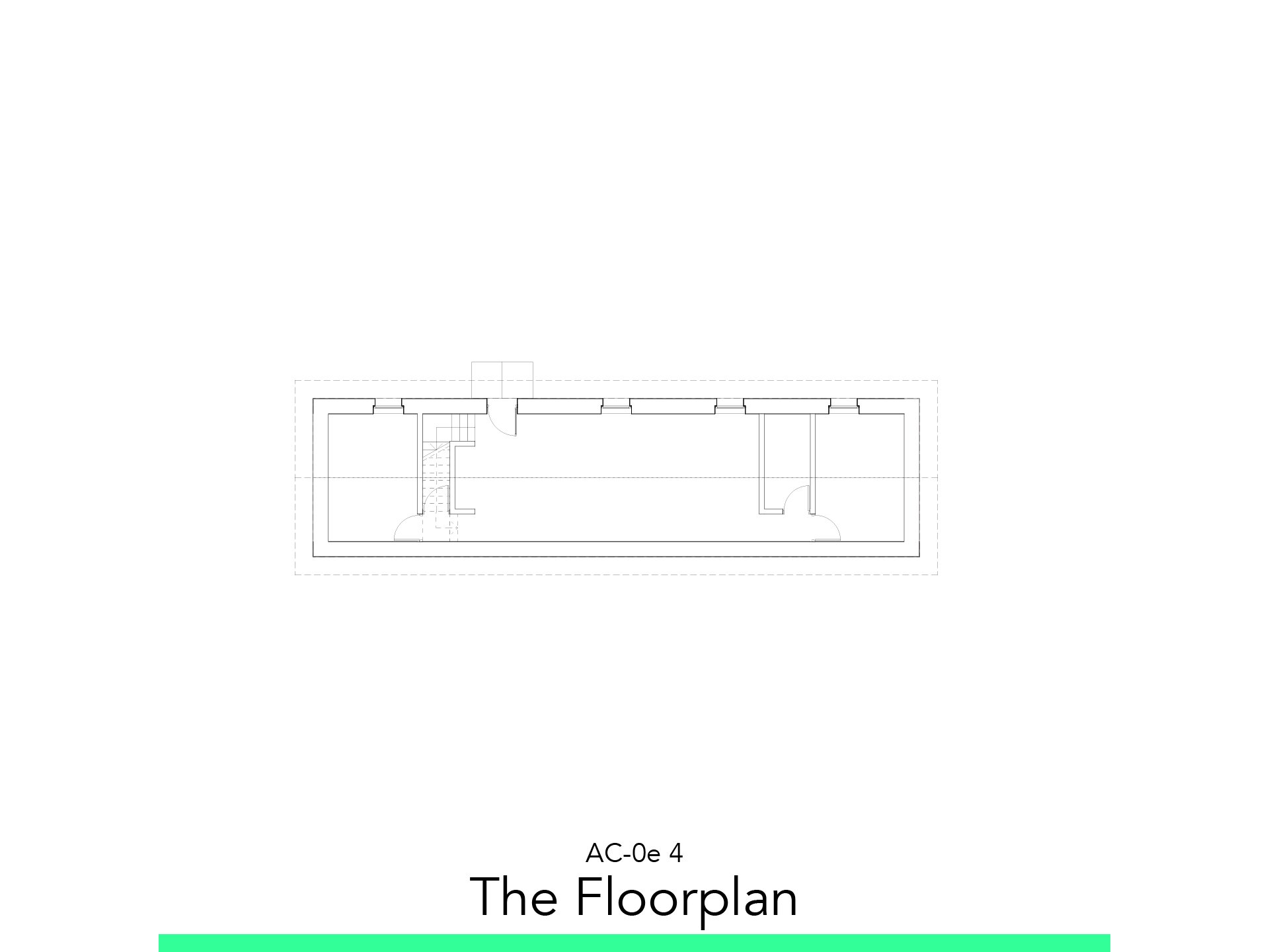
4. The Floorplan

4.1. Layout
Create a New View in the Organizer.
Go to the Layout Map > New Layout.
Adjust the Following Settings:
Master Layout: B A2 Landscape Blank
Insert the Floorplan View.
You have created the View, verify the values of Pen Set, Graphic Override and MVO.
Change View in Document > Floor Plan Cutplane, set following settings:
Cut Plan Height to Current Story: 1,00
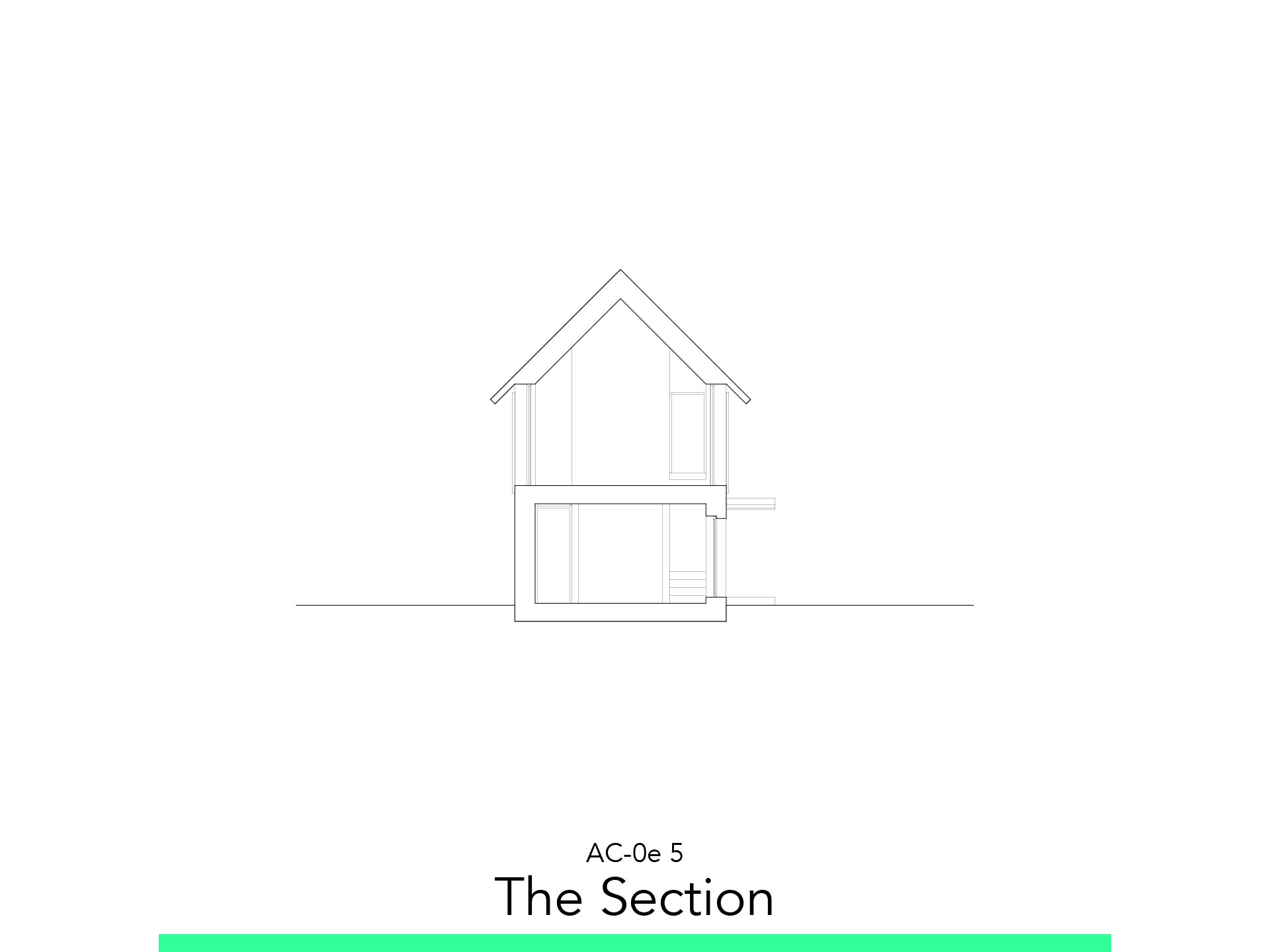
5. The Section

5.1. Section Marker
Go to the Toolbox > Document > Section Tool.
Trace the two points of the section.
Go to Section Settings > Horizontal Range > Limited Depth.
Edit the Depth till it covers all the building.
Go to the Project Map > Sections > Number of the Section.
You can create the View of the New Section.
You can left click on the Level Marker and Hide it.
5.2. Story Settings
Go to the Project Map.
Right click on Stories > Story Settings.
Modify the Ground Floor Height to Next: 4.00.
Verify how the Slab and the Walls change.
5.3. Hybrid Section
Create fill of terrain in Toolbox > Document > Fill Tool.
Assign the following settings:
Fill Pattern: Foreground
Fill Pen Foreground: 121
Fill Pen Background: -1
5.4. Layout
Create the New View in the Organizer.
Insert the View in the Layout created.
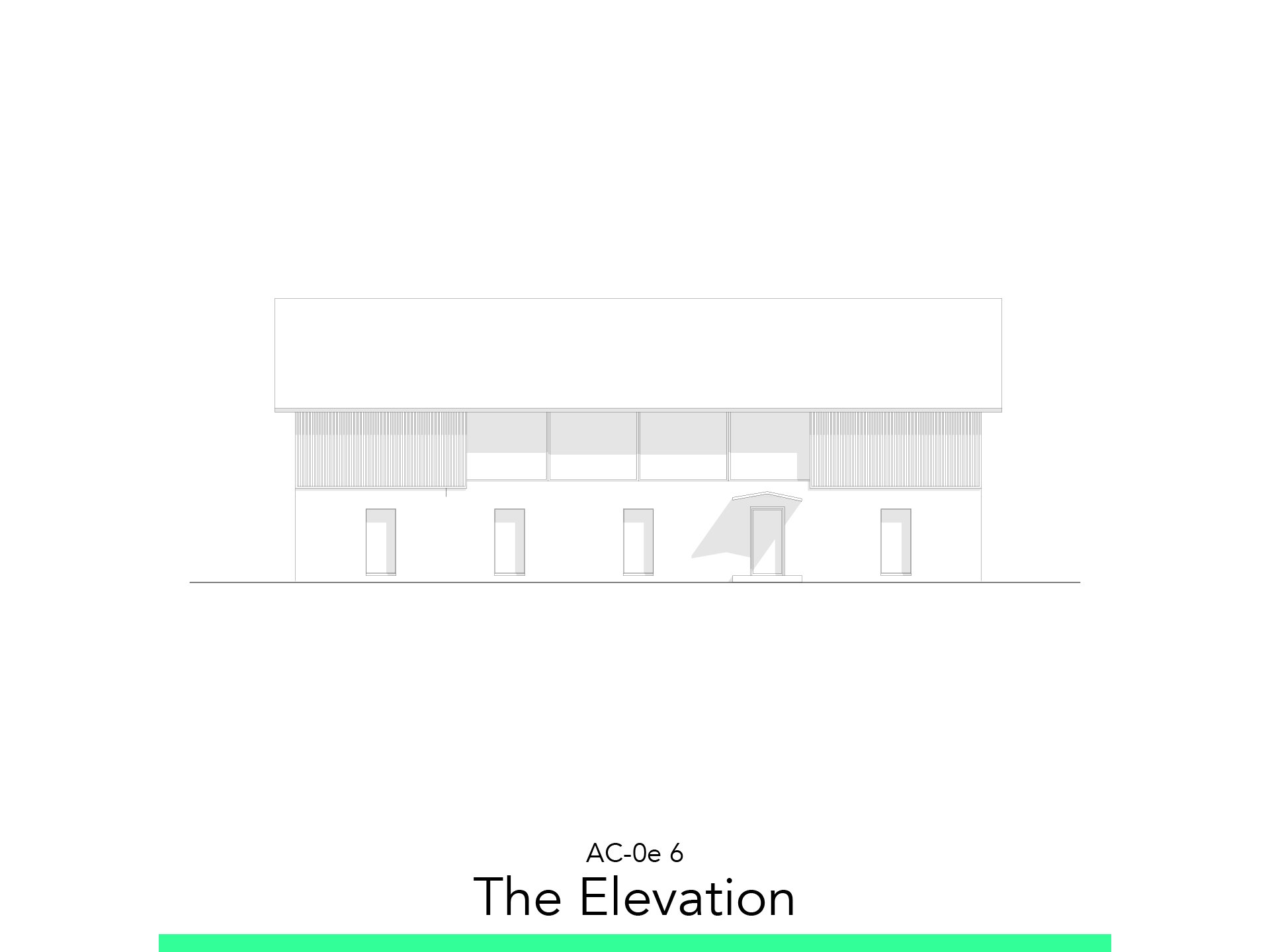
6. The Elevation

6.1. Elevation Marker
Go to the Toolbox > Document > Elevation Tool.
Trace the two points of the Elevation.
Go to Elevation Settings > Horizontal Range > Limited Depth.
Edit the Depth till it covers all the building.
Go to the Project Map > Elevations > Number of the Section.
You can create the View of the New Section.
6.2. Adjust Shadow
Go to the Project Map > Elevation Settings.
Go to Model Display > Sun and Shadows.
Adjust the following Settings:
Sun Azimuth: 45°
Sun Altitude: 45°
Sun Shadow: Checked
Shadow Polygons: 25%
Fill Pen: 101
Fill Background Pen: 0
6.3. Hybrid Elevation
Create fill in Toolbox > Document > Fill Tool.
Assign the following settings:
Fill Pattern: Foreground
Fill Pen Foreground: 121
Fill Pen Background: -1
6.4. Layout
Create the New View in the Organizer.
Insert the View in the Layout created.
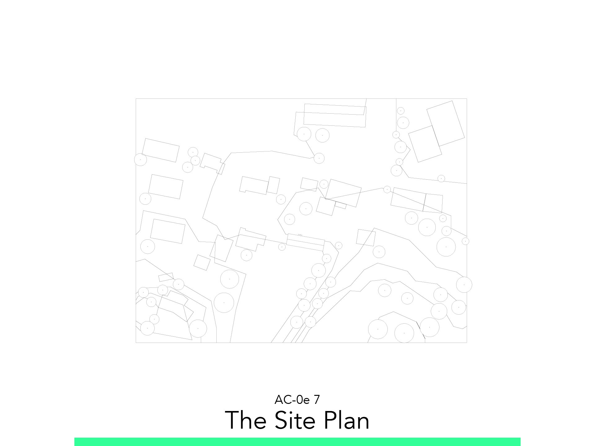
7. The Site Plan

7.1. Model Terrain
Go to Ground Floor.
Insert Site Plan JPEG in a New Worksheet.
Right click on Project Map > Worksheet > New Independent Worksheet…
File > External Content > Place External Drawing
Select the Site Plan in the Learning Material
Scale the plan
Create Mesh.
Trace simple topographic lines.
Create New Mesh Points:
Select Mesh.
Press Alt (Dropper) > Select Mesh
Press Space and Click on the drawn Topographic Line
A Window will open > Fit to All Ridges
Elevate the topographic lines fitted.
Select Mesh
Select one topographic line
Select on Pen Palette > Elevate Mesh Point
Assign Height to 2,0 meters
Check Apply to All
Elevate the corners to its more near topographic line.
Modify the height of the Mesh to fit in the model.
Enter the Mesh Settings > Floor Plan and Section
Floor Plan Display > Show on Stories > Home & One Story Up
Outlines > Ridge Selection > Show User Defined Ridges
7.2. Model Context
Start Slab Tool and Draw the Context.
You can put it in the Layer 106 Context Building Slabs.
Configurate Height and Elevation to fit in the context.
You locate the house in Google: 46.828868, 9.404528
Create the Roofs over the buildings.
Create Roofs that overlap the slabs.
Make Solid Element Operation to mold the context slabs.
7.3. Model Trees
Go to Object Tool > Search for > Conceptual Tree 22
Insert with reference of the location
Modify the size with the Pet Palette > Move Node
7.4. Create View (Graphic Override, Pen Set, MVO)
Create Site Plan View.
Enter View Settings and adjust the following settings:
Scale: 1:500
Pen Set: B04 Site 500
Model View Options: B01 Site
Graphic Override: B02 Site Plan
Change View in Document > Floor Plan Cutplane, set following settings:
Cut Plan Height to Current Story: 10,00
Show up to: 3 Stories
Story(s) above
Change Roof’s Floor Plan and Section:
Cover Fill: Foreground
Cover Fill Pen: 121
Cover Fill Background Pen: 121
7.5. Layout
Create the New View in the Organizer.
Insert the View in the Layout created.
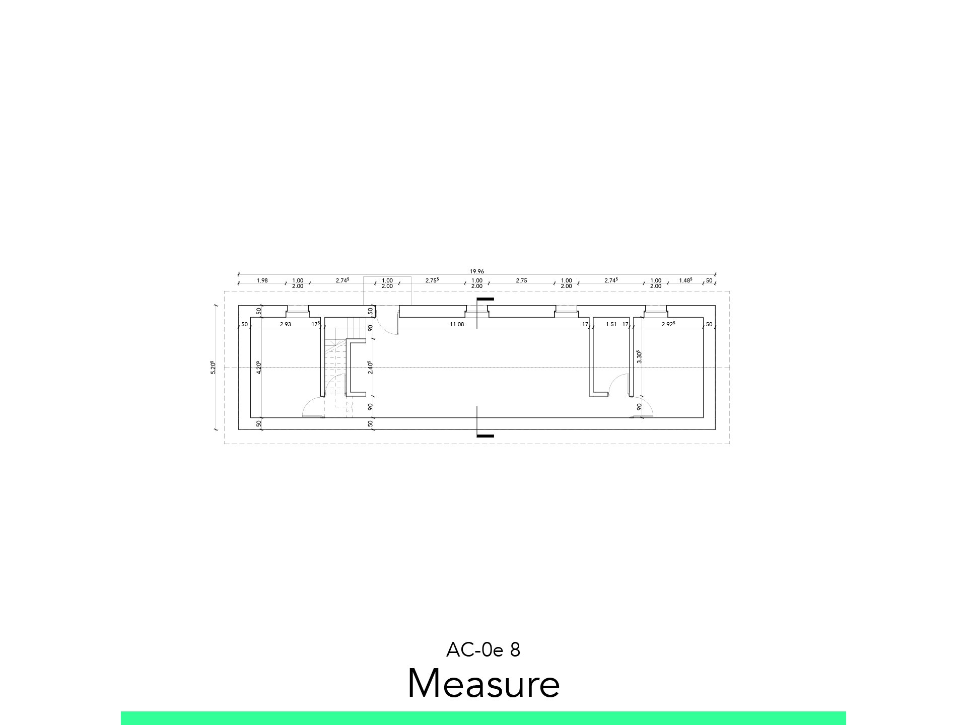
8. Measuring

8.1. Floor Plan
Go to the View created.
Go to Toolbox > Dimension Tool
Set the Dimension Settings:
Font Size: 1,7
Line and Marker Pens:
Dimension Line: 85
Dimension Marker: 45
Add simple 2D Markers of the Section.
You can add I in layer 306 Marker Sections.
8.2. Section
Go to the View created.
Go to Toolbox > Dimension Tool:
You can use the dropper with alt to save the last dimension created.
Set the Dimension Settings:
Font Size: 1,7
Line and Marker Pens:
Dimension Line: 85
Dimension Marker: 45
In Section the most important is the height, so don’t waste more dimension that aren’t required.
8.3. Elevation
Go to Toolbox > Dimension Tool
Set the Dimension Settings:
Font Size: 1,7
Line and Marker Pens:
Dimension Line: 85
Dimension Marker: 45
The Elevation it’s the most basic to be dimensioned, could be the windows and the roof.
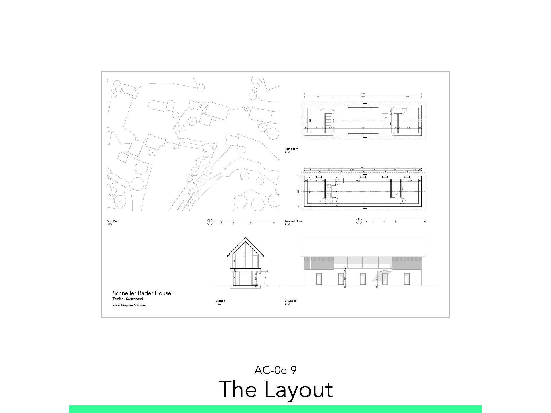
9. The Layout

9.1. Master Layout
Go to the Layout Map > Masters
Here you can see all the size we have available, in Portrait and Landscape.
You can use codes as #Layout Name that gets the name of the Layout so you don’t have to do the work twice.
9.2. Update Views
It’s better to don’t overcharge your computer to change in the View Settings > Update Type: Manual Update.
If you want to update right click on the view and click on Update.
9.3. Scale, North and Naming
You can set on the View Settings an automatic Tittle that types the name of the view and its scale.
Go to View Settings > Title > B Drawing Title
Or you can set it manually on > Tool Box >Document > Text Tool.
Use it to Create the Layout Title.
Draw the North with a Circle and a Line in Tool Box > Documents.
Set a thicker pen to the North pointer.
Draw the Scale of 1:100 and 1:500 thinking that 10mm in the Layout is 1m in 1:100 and 5m in 1:500.
9.4. Export
Go to the Publisher Sets next to the Layout Book.
Select the 2 – Layouts, and enter in Publishing Properties…
Adjust the following settings:
Create single file: Check
Format: PDF
Choose the location Path
Now you can enter in the Publish Set and select the Layout we create.
Select Publish.
Follow your study path with these recommended tutorials


Model in ArchiCAD for the absolute first time with me!
Let me teach you basic commands of the software for you to be ready work on your projects. Start from the very basics and follow me step-by-step in the process of giving more detail to your architectural model.