AC-1c Manual CADing Basics in ArchiCAD


About this Tutorial
This course is intended for first time ArchiCAD users who want to learn how to Manual CAD an architecture project. Self-taught users can also profit from these structures to consolidate essential concepts. You will find step-by-step explanations while we create our first Manual CADing in ArchiCAD, continuing the work we started in Modeling made in Ri-0a. We will take our modeled project and extract basic shapes from it which will help us trace the correct lines manually to express our project. In this unit you will learn the important skill of “The Line Weight” which will be crucial to the develop of CADing. Finally, we will scale and put our drawings in the Layout to be ready to print, show it and use it.
Skill level and duration
Level: First Time Users
Duration: A couple of hours
In this tutorial you will learn
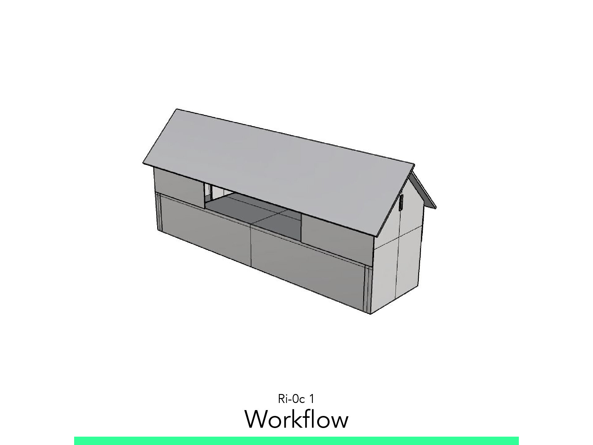
Workflow
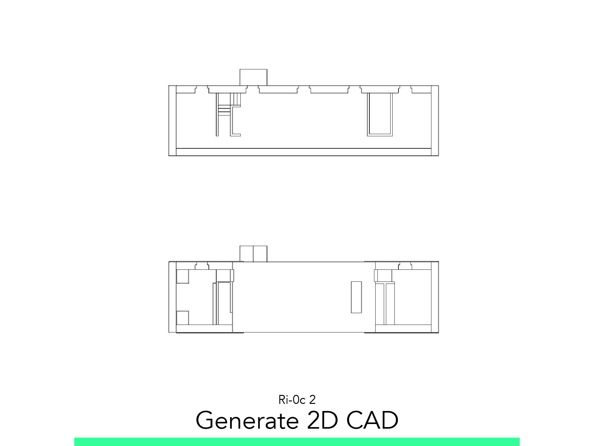
Generate 2D CAD
Layout
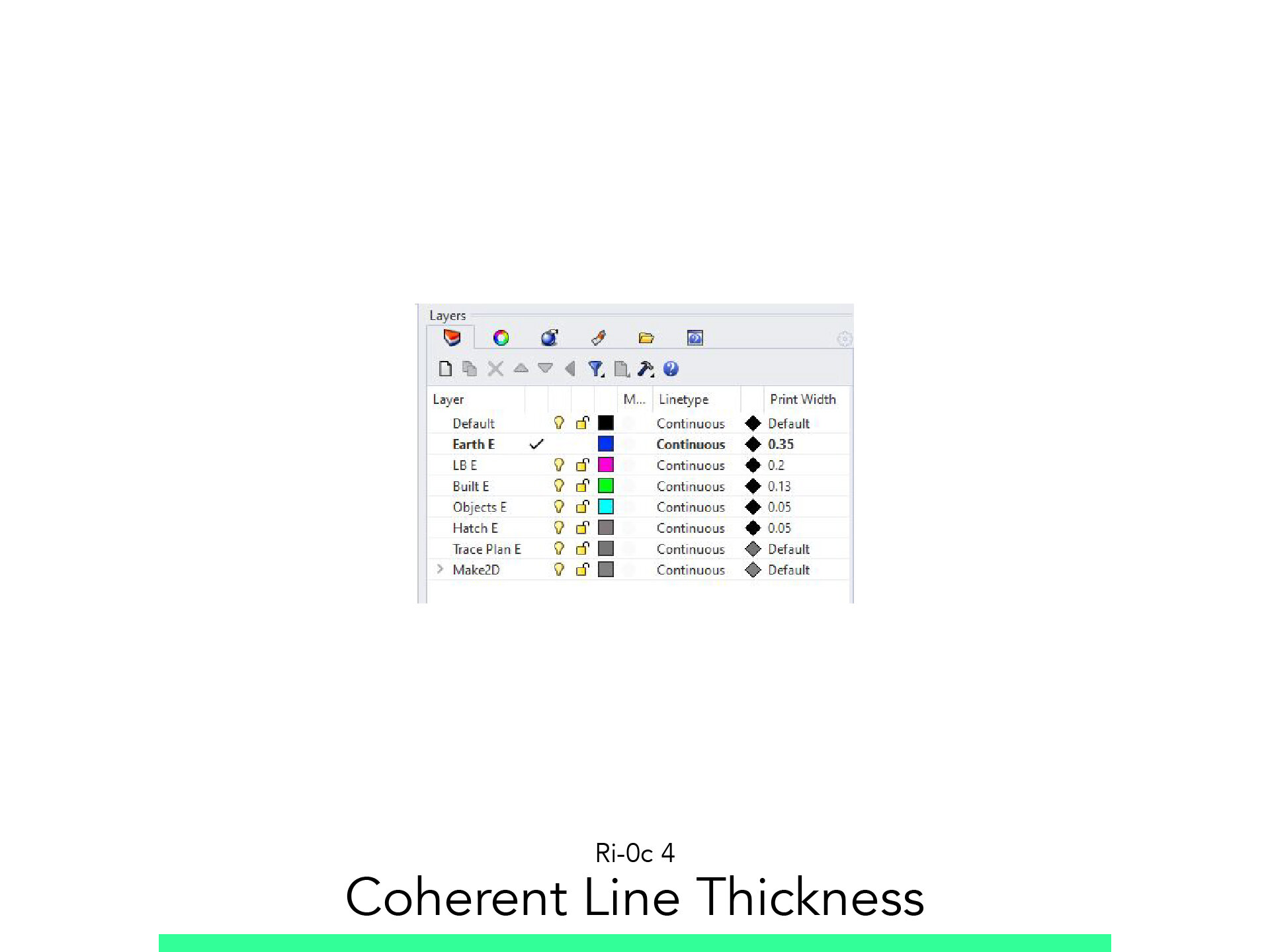
Coherent Line Thickness
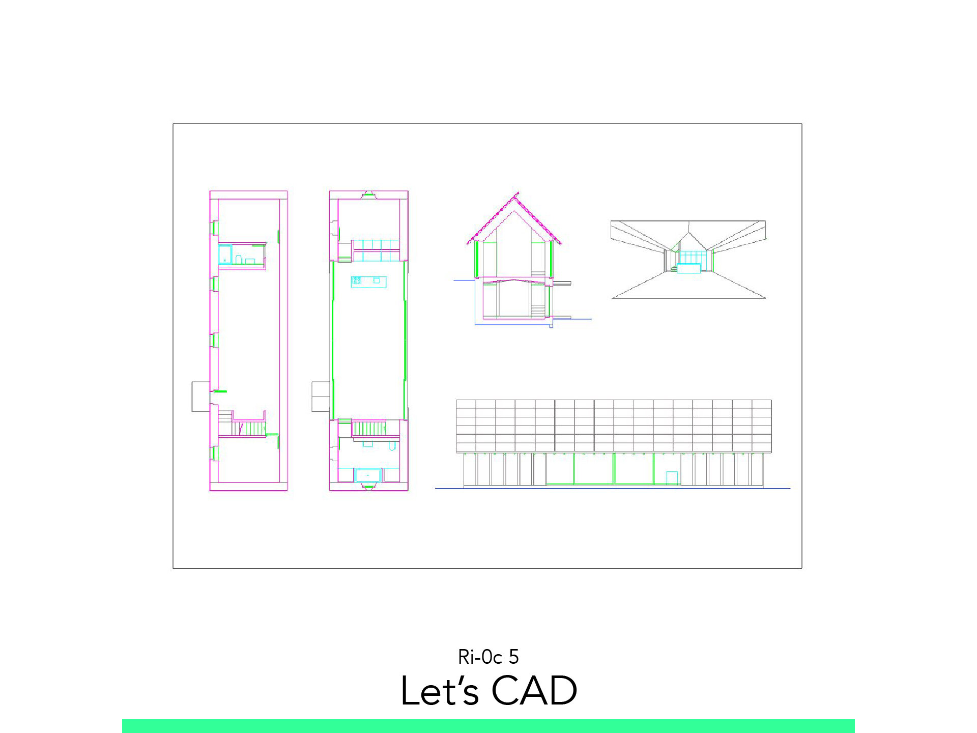
Let’s CAD
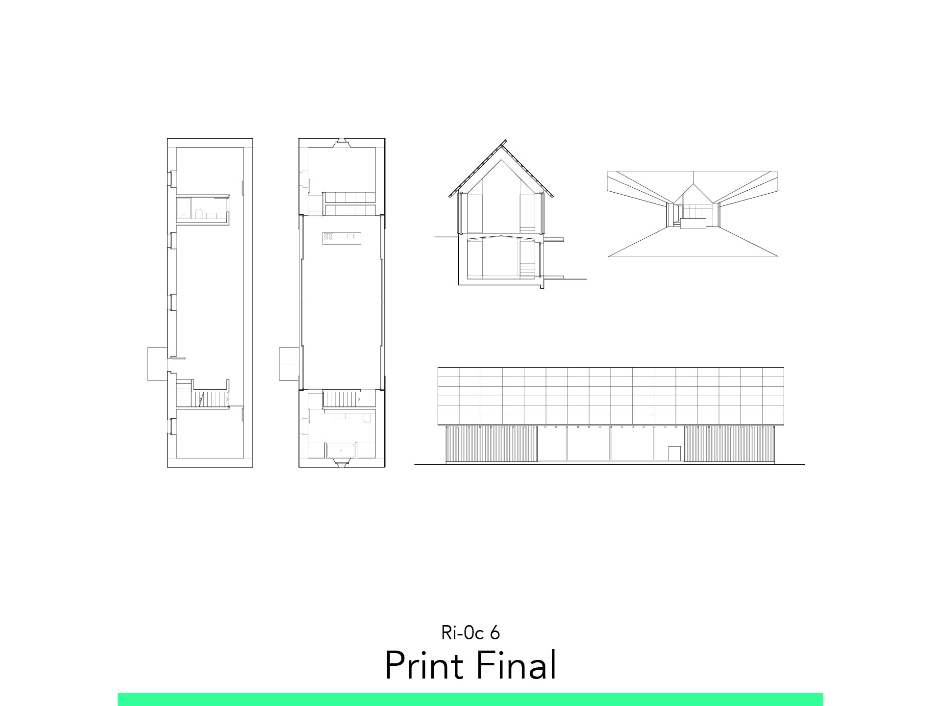
Print Final
The materials you will need
Your laptop with internet connection to download and install software during the course.
Tutorial content
• 6 Videos
• Full Tutorial Script
• Sample 3D File
Why take this tutorial
Manual CADing is a good first step to learn how to use ArchiCAD or any program to create plans. The skills you develop during Manual CADing while using the Line Weight are essential to develop a comprehensible architectural plan. The tasks and skills you develop here will be a great start in helping you develop more complex tasks in this program and also as an architectural designer.
1. Workflow

1.1. Generate 2D
The first step is to take the 3D Model we have created in the exercise Ri-0b and with great commands extract from it 2D CAD planes to use it and trace architecture plans.
1.2. Print
Then we are going to start the Layout sketch to view how are we going to present it.
1.3. Sketch by line type
Finally, we are going to establish the line thickness, color and category to know how we are going to trace over the 2D CAD we made from the 3D Model.
1.4. Start the CAD!
Now let’s align our mantras to start this quest of drawing our architecture plans.
1.5. Setup 4 Pens
To Set the 4 Pens go to: Options > Element Attributes > _Pens & Color.
You can set 4 pen sets with these sizes or check this numbers we have in our file.
N° 22: 0.35 mm
N° 42: 0.20 mm
N° 23: 0.13 mm
N° 3: 0.05 mm
2. Generate 2D CAD

2.1. Floorplans
Floor Plan Cut Plane.
Go to the Ground Floor.
To find it enter on Document > Floor Plan Cut Plane.
Adjust the following settings.
Cut Plane Height to Current Story: 1.00
Save Current View.
Go to the View Map.
To Save the View click on the Icon of: Save Current View.
Start Worksheet.
Go to the Project Map.
Click on the Worksheet category, then the Icon: New Viewpoint.
Adjust the following settings:
Reference ID: 2.a
Name: Ground Floor
Trace Reference
Go to the 2.a Ground Floor Worksheet.
Right click on the View we have just created: Show as Trace Reference.
Draw a simple Square of Reference. Toolbox > Polyline
1. Story Plan Cut Plane
Go to the 1. Story
To find it enter on Document > Floor Plan Cut Plane.
Adjust the following settings.
Cut Plane Height to Current Story: 1.00
Save Current View
Go to the View Map.
To Save the View click on the Icon of: Save Current View.
Start Worksheet
Go to the Project Map.
Click on the Worksheet category, then the Icon: New Viewpoint.
Adjust the following settings:
Reference ID: 2.b
Name: 1. Story
Trace Reference
Go to the 2.b 1. Story Worksheet.
Right click on the View we have just created: Show as Trace Reference.
Draw a simple Square of Reference. Toolbox > Polyline.
2.2. Section
Section Marker.
To create a Section: Toolbar > Document > Section Tool.
Go to the Project Map > Section > S-01.
Save Current View.
Go to the View Map.
To Save the View click on the Icon of: Save Current View.
Start Worksheet
Go to the Project Map.
Click on the Worksheet category, then the Icon: New Viewpoint.
Adjust the following settings:
Reference ID: 2.c
Name: Section
Trace Reference
Go to the 2.a Ground Floor Worksheet.
Right click on the View we have just created: Show as Trace Reference.
Draw a simple Square of Reference. Toolbox > Polyline.
2.3. Elevation
Elevation Marker.
To create a Section: Toolbar > Document > Elevation Tool.
Go to the Project Map > Elevation
Save Current View.
Go to the View Map.
To Save the View click on the Icon of: Save Current View.
Start Worksheet
Go to the Project Map.
Click on the Worksheet category, then the Icon: New Viewpoint.
Adjust the following settings:
Reference ID: 2.d
Name: Elevation
Trace Reference
Go to the 2.a Ground Floor Worksheet.
Right click on the View we have just created: Show as Trace Reference.
Draw a simple Square of Reference. Toolbox > Polyline
2.4. Perspective
3D Document.
Go to the 3D View
Isolate the Model. F5
Set the Inside View.
Select the Category of 3D Document: New Viewpoint
Adjust the following settings
Reference ID: 2e
Name: Perspective
Save Current View.
Go to the View Map.
To Save the View click on the Icon of: Save Current View.
Start Worksheet
Go to the Project Map.
Click on the Worksheet category, then the Icon: New Viewpoint.
Adjust the following settings:
Reference ID: 2.e
Name: Perspective
Trace Reference
Go to the 2.a Ground Floor Worksheet.
Right click on the View we have just created: Show as Trace Reference.
Draw a simple Square of Reference. Toolbox > Polyline
3. Layout

3.1. Paper Space
Go to the Layout Book.
Create a New Layout: A3 Landscape.
Go to the Project Map.
Insert in the Layout the Worksheets.
Rotate and Move it to visualize the Layout.
5. Let’s CAD

5.1. Ground Floor
Worksheet:
Create a New Worksheet with the name: 4.a Ground Floor
Using CAD Tools:
Trace with polyline. Toolbar > Document > Polyline
Trace a Circle Toolbar > Document > Circle
Using CAD Modifiers:
Use Snaptrack to follow the Model. SnapTrack
Trim: Ctrl + Click
Check your Sketch, think… and Draw!
5.2. 1. Story
Worksheet:
Create a New Worksheet with the name: 4.b 1 Story
Using CAD Tools:
Trace with polyline. Toolbar > Document > Polyline
Using CAD Modifiers:
Use Snaptrack to follow the Model. SnapTrack
Trim: Ctrl + Click
Check your Sketch, think… and Draw!
5.3. Section
Worksheet:
Create a New Worksheet with the name: 4.d Section
Using CAD Tools:
Trace with polyline. Toolbar > Document > Polyline
Using CAD Modifiers:
Use Snaptrack to follow the Model. SnapTrack
Trim: Ctrl + Click
Check your Sketch, think… and Draw!
5.4. Elevation
Worksheet:
Create a New Worksheet with the name: 4.c Elevation
Using CAD Tools:
Trace with polyline. Toolbar > Document > Polyline
Trace the Wood Façade. Toolbar > Document > Fills
Adjust the following settings:
Fill Pattern: Vertical Lines 15
Fill Pen: Foreground 1 – 0.05 mm
Contour Pen: 23 – 0.13 mm
Construction Method: Distorted Fill
Trace the Roof Pattern. Toolbar > Document > Fills
Adjust the following settings:
Fill Pattern: Rigid Isulation
Fill Pen: Foreground 1 – 0.05 mm
Contour Pen: 23 – 0.13 mm
Construction Method: Distorted Fill
Using CAD Modifiers:
Use Snaptrack to follow the Model. SnapTrack
Trim: Ctrl + Click
Check your Sketch, think… and Draw!
5.5. Perspective
Worksheet:
Create a New Worksheet with the name: 4.e Perspective
Using CAD Tools:
Trace with polyline. Toolbar > Document > Polyline
Using CAD Modifiers:
Use Snaptrack to follow the Model. SnapTrack
Trim: Ctrl + Click
Check your Sketch, think… and Draw!
6. Print Final

6.1. Paper Space
Go to the Layout Book.
Create a New Layout.
Adjust the following settings:
Layout Name: 06 Layout
Master Layout: A3 Landscape
6.2. Insert Views
Go to the View Map.
Click and drag the Worksheets we have created over the Layout.
Change the Scale of the plans to: 1:100
Axonometry to: 20%
To Move it: Ctrl + D
6.3. Export PDF
You can Save the PDF Ctrl + Shift + S.
Or go to Publisher Sets > Layouts > Publishing Properties:
Publishing Method: Save files
Create Single File
Format: PDF
Name: AC-0c_PDF
Follow your study path with these recommended tutorials


Model in ArchiCAD for the absolute first time with me!
Let me teach you basic commands of the software for you to be ready work on your projects. Start from the very basics and follow me step-by-step in the process of giving more detail to your architectural model.