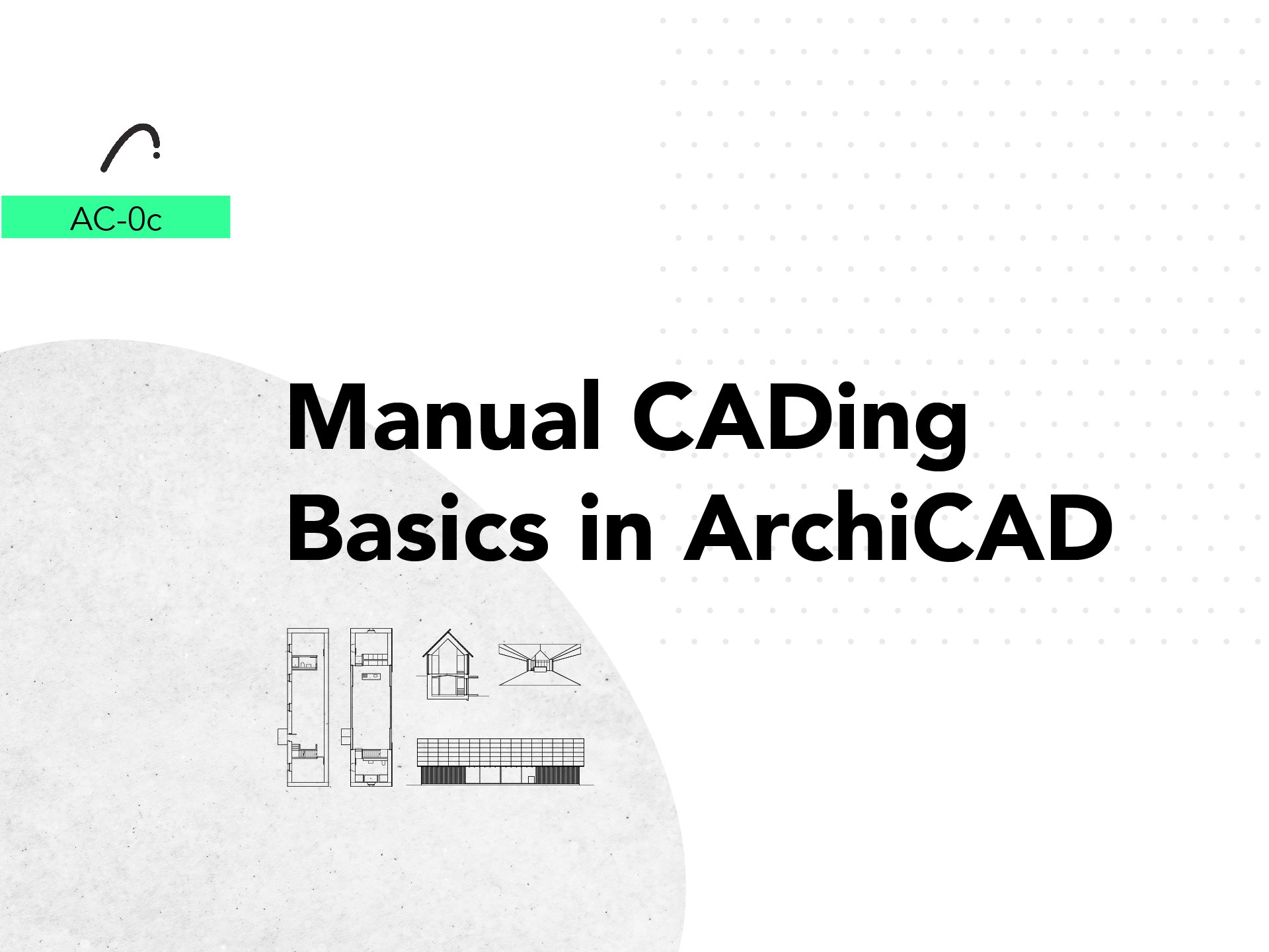
W-1c
Intro to 3D-Based CADing for Architecture Design
Deep Dive into CADing with a focus on how we, architects, can take the most advantage of it. Gain confidence in the subject even if you have never tried it. Understand the fundamental values that we require as creators to fully express and create Architecture Drawings by practicing with simple, step by step exercises.
Support your design process by slowly implementing 3D based CADing as a design tool by first understanding what CAD is, and what it can do. This course will take you through the history of CAD and how to take advantage of a rough 3D model, learn how to use Line Weight with a practical exercise, then draw it digitally, and finally insert it in your final sheet to be available to print and present.
-
![]()
Exercise 1
2D CAD Tools
-
![]()
Exercise 2
2D CAD Modifiers
-
![]()
Exercise 3
Fiils
-
![]()
Exercise 4
Make 2D
-
![]()
Exercise 7
Axonometry
-
![]()
Exercise 8
The Layout


About the course
This course is intended for architects who want to integrate 3d based CADing into their design process and have some extra time to dive into the subject. We will start by understanding the mechanics of it, its history, the different methods, and most importantly how it can be integrated into helping clients, professors or colleagues understand your architectural idea.
Skill level and duration
Intended for the curious and the absolute beginners, or for self-taught users who would like to restart with a fresh structure.
The course is 8 chapters long, each with a lecture of no more than 20 minutes and an integrated practical exercise, each requiring between 30 to 45 minutes. In total, allow for three full afternoons.
Recommended Next Step Tutorials
Follow these Tutorials to practice and develop the skills learned here to create a full Manual CADing work in a unified architecture project.

In this course you will learn
The Story of AutoCAD.
Scale in Architecture Drawings.
Drawing Depth.
The Floorplan.
The Section.
The Elevation.
The Axonometry.
The Layout.
The materials you will need
Latest Version of Rhino or ArchiCAD, Installed and Running (necessary).
Basic understanding of Rhino, or Complete the Course “Ri-0 Rhino Foundations” or “AC-0 ArchiCAD Foundations” (necessary).
High performance computer (optional).
Course Content
8 Videos.
One single file with all the exercises.
Full Tutorial Script with searchable commands.
0. General CAD Concepts
To start to learn about CADing its crucial to learn the foundations of the program you are going to work. So you can easily relate to a really tricky interface, with a lot of tools, commands, orders and configurations. You will spend a lot of time just watching and traveling around the program but trust me this will be realy useful in the future so you dont’t waste so much something punctual that we are going to see in this course.
Choose your software and follow the excercise
IMPORTANT NOTE: If you have never opened Rhino or would like to get a foundational understanding of the Software, I invite you to follow this link to the Foundations Tutorial of Rhino It will be a good hour spent either learning how to navigate it or furthering your knowledge.
If you have never opened ArchiCAD or would like to get a foundational understanding of the Software, I invite you to follow this link to the Foundations Tutorial of ArchiCAD. It will be a good hour spent either learning how to navigate it or furthering your knowledge.
If you have never opened ArchiCAD or would like to get a foundational understanding of the Software, I invite you to follow this link to the Foundations Tutorial of ArchiCAD. It will be a good hour spent either learning how to navigate it or furthering your knowledge.
1. The Story of AutoCAD
Wassily Kandinsky’s stated: “Everything starts from a dot” and “a line its a succession of repetitive dots”. In this chapter we are going to learn how to create a line, an arc, a polyline and how to change its color and figure. The CAD work is as simple as that, A LOT of lines that have different characteristics which work together to create a concrete drawing, a concrete expression, or a concrete idea.

Choose your software and follow the exercise

Rhino Script
1. Line
Start command Line.
Select the Start of the Line on the Model.
Select the End of the Line on the Model.
2. Arc
Start command Arc.
To start from a Start Point type StartPoint.
Select the Start of the Arc on the model.
Select the Middle Point of the Arc.
Press Enter.
Repeat again with a more concave Point of Arc.
3. Polyline
Start command Polyline.
Select the Start of the Line on the Model.
Select the Next Points of the Polylline.
To finish the Polyline press Enter.
4. Layer
Go to Layer Tab on the Right Side of the Screen.
Click on the New Layer Icon.
Write the Name of the Layer.
Start command ChangeLayer.
Select the Line that will be changed.
Select the Layer you want to move.
You can do it also in the icon at the lower part of the screen or also in the Properties Tab in the right side of the window.
5. Line Type
Start command SetLinetype.
Select the Curve.
On the Window Select the Linetype.
You can do it also in the Properties Tab in the right side of the window.

ArchiCAD Script
1. Line
To create a Line Toolbox > Line
Select the Start of the Line on the View.
Select the End of the Line on the View.
2. Arc
To create Arc. Toolbox > Polyline
To create the curve select: PP > Arc with defined tangent
Select a far tangent to create a bigger curve.
3. Polyline
To create the Polyline: Toolbox > Polyline
Select the Start of the Line on the Model.
Select the Next Points of the Polyline.
4. Pen
To change Color go to Properties > Pen.
Change to Color N° 95
5. Line Type
To change Linetype go to Properties > Linetype
Change to Linetype Dot & Dashed
ArchiCAD CHE Script
1. Line
To create a Line Planung > Linien
Select the Start of the Line on the View.
Select the End of the Line on the View.
2. Arc
To create Arc: Planung > Polylinien
To create the curve select: PP > Segment mit derTangente
Select a far tangent to create a bigger curve.
3. Polyline
To create the Polyline: Planung > Polylinien
Select the Start of the Line on the Model.
Select the Next Points of the Polyline.
4. Pen
To change Color go to Einstellungen > Stift
Change to Color N° 95
5. Line Type
To change Linetype go to Einstellungen > Linientyp
Change to Linetype Strichpunk
2. Scales in Architecture Drawings
Now that we have created our lines, we need to learn how to transform and manipulate them. It is important to understand how to use these tools to configure the lines you have created both in an open space and within the complex group of lines that it inhabits, while giving them more cohesion to express an architecture idea.

Choose your software and follow the exercise

Rhino Script
1. Snap Points
Start command Move
You can use M as shortcut.
To Snap End Check the box End.
Locate on the lower part of the screen.
Or you can write in the command bar End.
Select the Vertical and move it near the Horizontal Line.
To Snap Middle:
Locate on the lower part of the screen.
Or you can write on the command bar Mid.
It will snap to create a T Shape.
2. SmartTrack
Start command SmartTrack.
To turn it on = On.
Start command Move.
Select the Vertical Line and take it.
Put the cursor at the Right End of the Horizontal Line.
A white Circle will appear under the cursor.
You can move the cursor by Ortho and the Reference will appear.
3. Offset
Start command Offset.
Select the Curve to Offset.
Write Offset Value = 5.
Press Enter.
4. Trim
Start command Trim.
Select one rectangle as cutting object.
Select the Line inside the Rectangle to Trim.
Select the Trimmed Rectangle and trim the lines of the other one.
5. Extend
Start command Extend.
Select the Horizontal Line as the Boundary Object.
Press Enter.
Select the Vertical Line as the Curve to Extend.
Press Enter.
6. Array
Start command ArrayCrv.
Select the Circle as the Object to Array.
Press Enter.
Select the Line as the Path Curve.
You can choose the array as Number of Items or Distance.
Distance = 7
Items = 9

ArchiCAD Script
1. Snap Guides and Points
Activate the Snap Guides and Points icon Standard Toolbar
You can find it in: Window > Toolbar > Standard
Move the vertical Polyline with: Ctrl + D
It will appear a middle guide for you to snap on.
2. SmartTrack
Move the Vertical Polyline with: Ctrl + D
Place the cursor over the final point as reference until it appears a closed circle.
You can now move it with reference of this polyline.
3. Offset
Select the polyline then: PP > Offset All Edges
To Copy the polyline you are going to create: Ctrl
Enter the Value: 3.00.
4. Trim
To Start to Trim press: Ctrl
A scissors Icon will appear.
Select the crossed lines inside the boxes.
5. Stretch
Select the Vertical Polyline.
Select the upper point, then: PP > Stretch.
Place it perpendicular to the Horizontal Line.
6. Multiply
Select the Circle and his point. PP > Multiply.
A window will open, select: Drag
Establish the distance between each circle.
Now move the cursor to multiply the circle.
ArchiCAD CHE Script
1. Snap Guides and Points
Activate the Snap Guides and Points icon Fanghilfen und -punkte
You can find it in: Optionen> Fanghilfen und -punkte or (Alt+F)
Move the vertical Polyline with: V
It will appear a middle guide for you to snap on.
2. SmartTrack
Move the Vertical Polyline with: V
Place the cursor over the final point as reference until it appears a closed circle.
You can now move it with reference of this polyline.
3. Offset
Select the polyline then: PP > Alle Kanten versetzen
To Copy the polyline you are going to create: i
Enter the Value: 3.00.
4. Trim
To Start to Trim press: Stgr
A scissors Icon will appear.
Select the crossed lines inside the boxes.
5. Stretch
Select the Vertical Polyline.
Select the upper point, then: PP > Knotenpunkt verschieben.
Place it perpendicular to the Horizontal Line.
6. Multiply
Select the Circle and his point. PP > Multiplizieren.
A window will open, select: Verschieben
Stablish the distance between each circle.
Now move the cursor to multiply the circle.
3. Drawing Depth
We are now entering the next level, a full two-dimensional mass constructed of more that two points. Fills are a really helpful tool for the CAD drawing of architecture. Here you will learn how to create them, transform them and give them more complexity. Later, you will understand why this tool is so useful in helping produce the architecture project.
Choose your software and follow the exercise

Rhino Script
1. Fill Type
Start command Hatch.
Select the Rectangle as the Curve.
Press Enter.
A window will open, select: Grid60.
Press Ok.
2. Filling
Start command Hatch.
Select the Rectangles as Curves.
Boundary = Yes.
Select the Inside Region.
Press Enter.
A window will open: Select Solid.
Press Ok.
3. Controlling Color
Select the Hatch Created.
Go to the Properties Tab and change Display Color.
4. Dividing
Start command Trim.
Select the Horizontal Line as the Cutting Object.
Select the Upper part of the Hatch to Trim.
Press Enter.
5. Hatch Edit
Start command PointsOn.
Select the Hatch.
The Control Points will Appear, select the two upper ones.
Start command Move.
Move it to the upper border of the Square.

ArchiCAD Script
1. Fill
To create a fill go to: ToolBox > Fill Tool.
Draw a square.
Select the fill and change the Fill Pattern to: Dot & Dashed.
Change Fill Pen Pattern to: 82.
2. Filling
To create a Fill go to: ToolBox > Fill Tool.
To activate the Magic Wand press: Space.
Create the Fill Inside the Big Square.
Select the Fill we have just created, then: PP > Substract from Polygon.
Activate the Magic Wand to substract the Small Square. Space.
3. Controlling Color
Select the Fill Created.
Go to the Properties and change Fill Pattern Color > 95.
4. Split
Select the Fill, and activate Split: Edit > Reshape > Split.
Select the Horizontal Line as the Cutting Object.
5. Fill Edit
Select the Fill, then transform it: PP > Offset Edge.
Select the example as reference of Height.

ArchiCAD CHE Script
1. Fill
To create a fill go to: Planung > Schraffur
Draw a square.
Select the fill and change the Fill Pattern to: Strichpunk.
Change Fill Pen Pattern to: 82.
2. Filling
To create a Fill go to: Planung > Schraffur.
To activate the Magic Wand press: Leertaste.
Create the Fill Inside the Big Square.
Select the Fill we have just created, then: PP > Vom Polygon abziehen.
Activate the Magic Wand to substract the Small Square. Leertaste.
A window will open, select: Solid
Press OK
3. Controlling Color
Select the Fill Created.
Go to the Properties and change Fill Pattern Color > 95.
4. Split
Select the Fill, and activate Split: Ändern > Spliten.
Select the Horizontal Line as the Cutting Object.
5. Fill Edit
Select the Fill, then transform it: PP > Kanten versetzen.
Select the example as reference of Height.
4. The Floor Plan
Here is where we will answer the question of “How do I extract a Floor Plan of a 3D Model?” Don’t panic, it’s not rocket science, just watch and read our instructions correctly and you will be dominating this skill. The Make2D and View commands are important elements in Rhino and ArchiCAD respectively, so remember these tools, you will use them a lot! Next, we are going to practice the skills we have previously developed, so we are going to trace manually the shapes we created with the Make2D and View commands.
Choose your software and follow the exercise

Rhino Script
1. Make 2D
Start command ClippingPlane.
Trace the Rectangle in the Top View.
Move the ClippingPlane in the perspective View to cut the Frist Floor.
Select the Clipping Plane and check to see it in: Perspective.
Select the Building and start command Make2D.
A Window will appear and check it is in View: Top.
Press Ok and will appear the 2D Trace near the Point 0 of the Plan.
2. Freeze Layer and Change to Grey
Create a New Layer for the Trace Plan.
Go to Layer’s Tab on the right side of the Screen and change the color of the New Layer to Grey in the Square, next to the Padlock.
Lock the Padlock of the New Layer.
Take the 2D Created and start command ChangeLayer.
Select the New Layer.
Go to the Properties Tab and change Display Color to: By Layer.
3. Trace
Start command Polyline.
Ungroup and copy Lines.
Create the Polyline in the Layer created in the step 1.4.
Trace the Wall Cut.
Create the Hatch of the Wall in the Default Layer.

ArchiCAD Script
1. Floor Plan Cut Plane
To find it enter on Document > Floor Plan Cut Plane.
Adjust the following settings.
Cut Plane Height to Current Story: 1.00
2. Save Current View
Go to the Organizer.
To Save the View click on the Icon of: Save View >>>
3. Start Worksheet
Go to the Project Map.
Click on the Worksheet category, then the Icon: New Viewpoint.
Adjust the following settings
Reference ID: 04
Name: Ground Floor
4. Trace Reference
Go to the W-01 Ground Floor.
Right click on the View we have just created: Show as Trace Reference.
5. Let’s CAD
Trace with: Toolbar > Document > Polyline
Toolbar > More > Spline Tool
Adjust the following settings.
Pen: 1 - 0.13

ArchiCAD CHE Script
1. Floor Plan Cut Plane
Go to the 1. Obergeschoss.
Look in the main Menu Verwaltung > Grundriss-Schnittebene.
A window will appear, set the Schnittebenenhohe zu aktuellem Geschoss to 1.00.
2. Save Current View
Go to the Organisator Vebergen.
To Save the View click on the Icon of: Ausschnitt sichern >>>
3. Start Worksheet
Go to the Projekt-Mappe.
Click on the Worksheet category, then the Icon: Neues Unabhängiges Arbeitsblatt.
Adjust the following settings
Reference ID: 04
Name: Ground Floor
4. Trace Reference
Go to the arbeitsblatt AB-01 Erdgeschoss.
Right click on the View we have just created: Als Transparentpause anzeigen.
5. Let’s CAD
Trace with: Planung > Polylinien and Planung > Spline
Adjust the following settings.
Stift: 1 - 0.13
5. The Section
Now let’s explore the Section. This seems similar to the floor plan but you have to add another essential tool, The Section Tool. The tool gives us the idea of what is the relevance of a section, and where we should put it to better express the project. There is a difference in how you measure the Section: this plan gives you information on the constructive elements’ heights and it allows you to see the proportion of the space in its relation to the ground floor.
Choose your software and follow the exercise

This Step is no different than point 4.

ArchiCAD Script
1. Section Marker
To create a Section: Toolbar > Document > Section Tool.
Go to the Project Map > Section > S-03.
2. Save Current View
Go to the View Map.
To Save the View click on the Icon of: Save Current View.
3. Start Worksheet
Go to the Project Map.
Click on the Worksheet category, then the Icon: New Viewpoint
Adjust the following settings:
Reference ID: 05
Name: Section
4. Trace Reference
Go to the Project Map.
Click on the Worksheet category, then the Icon: New Viewpoint.
Adjust the following settings:
Reference ID: 05
Name: Section
5. Let’s CAD
Trace with:
Toolbar > Document > Polyline
Toolbar > More > Spline Tool
Adjust the following settings.
Building Pen: 1 - 0.13
Earth Pen: 22 – 0.35

ArchiCAD CHE Script
1. Section Marker
To create a Section: Planung > Schnitt > Schnitt Werkzeug
Go to the Projekt-Mappe > Schnitte > S-03.
2. Save Current View
Go to the Ausschnitt-Mappe.
To Save the View click on the Icon of: Ausschnitt sicher >>>
3. Start Worksheet
Go to the Projekt-Mappe
Click on the Arbeitsblätter category, then the Icon: Neues Unabhängiges Arbeitsblat
Adjust the following settings:
Reference ID: 05
Name: Schnitt
4. Trace Reference
Go to the arbeitsblatt AB-01 Erdgeschoss.
Right click on the View we have just created: Als Transparentpause anzeigen
5. Let’s CAD
Trace with:
Planung > Polylinien
Planung > Spline
Adjust the following settings.
Building Stift: 1 - 0.13
Earth Stift: 22 – 0.35
6. The Elevation
We are adding an interesting feature to tracing the line position and to understanding the relationship of heights with the ground: Shadows. This feature wouldn’t be so important in a section, but in a facade it shows the proximity and textures of the elements, and it is important in expressing any proposal of a facade in architecture.

Choose your software and follow the exercise

This Step is no different than point 4.

ArchiCAD Script
1. Elevation Marker
To create a Section: Toolbar > Document > Elevation Tool
Go to the Project Map > Elevation > E-01
2. Save Currrent View
Go to the View Map.
To Save the View click on the Icon of: Save Current View
3. Start Worksheet
Go to the Project Map
Click on the Worksheet category, then the Icon: New Viewpoint
Adjust the following settings
Reference ID: 06
Name: Elevation
4. Trace Reference
Go to the W-01 Ground Floor.
Right click on the View we have just created: Show as Trace Reference
5. Let’s CAD
Trace with: Toolbar > Document > Polyline
Adjust the following settings
Building Pen: 1 - 0.13
Earth Pen: 22 – 0.35

ArchiCAD CHE Script WIP!
7. The Axonometry
An axonometry is a schematic representation of the shape and objectives of a project. It may not be needed for constructive reasons but it is crucial for explaining a project and an idea. We can find thousands of architecture offices that make axonometries to summarize and express their projects. Pezo Von Ellrichausen’s work and their use of axonometries is a good example of how to represent architectural projects. In this unit we will create another Make2D in Rhino and a 3D View in ArchiCAD so be ready to learn to use another tool and to explore a different way to think about and develop a project.

Choose your software and follow the exercise

Rhino Script
1. Setting a Custom Axonometry
Go to the Perspective View and Click on the Down Arrow.
To Change View: Set View > Isometric > SE.
You can Rotate the View as you want it.
To Create and Check Views start command NamedView.
Click to Save New View as Custom Axonometry.
You can Change the View in this Window.
Select the Building and start command Make2D.
A Window will appear and check it is in View: CustomAxo
Press Ok and it will appear the 2D Trace near the Point 0 of the Plan.
2. Setting 45° Angles
Go to the Perspective View and Click on the Down Arrow.
To Change View: Set View > Isometric > SE.
To Create and Check Views start command NamedView.
Click to Save New View as 45.
You can Change the View in this Window.
Select the Building and start command Make2D.
A Window will appear and check it is in View> 45.
Press Ok and will appear the 2D Trace near the Point 0 of the Plan.
3. Setting Asymmetric 60°
Go to the Perspective View and Click on the Down Arrow.
To Change View: Set View > Isometric > SE.
Start command Rotate.
Select the House and set the Angle: -15.
To Create and Check Views start command NamedView.
Click to Save New View as 60.
Select the Building and start command Make2D.
A Window will appear and check it is in View: 60.
Press Ok and will appear the 2D Trace near the Point 0 of the Plan.

ArchiCAD Script
1. 3D Document
Go to the 3D View.
Isolate the Model. F5
Change to Axonometry: 3D Visualization Toolbar > Axonometry
Select the Category of 3D Document: New Viewpoint
Adjust the following settings:
Reference ID: 3D
Name: Perspective
Go to the Project Map > 3D Document > 3D-01.
2. Save Current View
Go to the View Map.
To Save the View click on the Icon of: Save Current View
3. Start Worksheet
Go to the Project Map.
Click on the Worksheet category, then the Icon: New Viewpoint
Adjust the following settings
Reference ID: 07
Name: Axonometry
4. Trace Reference
Go to the Project Map.
Click on the Worksheet category, then the Icon: New Viewpoint
Adjust the following settings
Reference ID: 07
Name: Axonometry
4. Let’s CAD
Trace with:
Toolbar > Document > Polyline
Toolbar > More > Spline Tool
Adjust the following settings:
Building Pen: 1 - 0.13
Earth Pen: 22 – 0.35

ArchiCAD CHE Script
1. 3D Document
Go to the 3D View.
Isolate the Model. F5
Change to Axonometrie: 3D Visualization Toolbar > Axonometrie
Select the Category of 3D Document: Neues 3D-Dokument aus 3D
Adjust the following settings:
Referenze-ID: 3D
Name: Perspective
Go to the Projekt-Mappe > 3D-Dokumente > 3D-01.
2. Save Current View
Go to the Ausschnitt-Mappe.
To Save the View click on the Icon of: Ausschnitt sicher >>>
3. Start Worksheet
Go to the Projekt-Mappe.
Click on the Arbeitsblätter category, then the Icon: Neues Unabhängiges Arbeitsblat
Adjust the following settings
Referenze-ID: 07
Name: Axonometry
4. Trace Reference
Go to the arbeitsblatt AB-01 Erdgeschoss.
Right click on the View we have just created: Als Transparentpause anzeigen
4. Let’s CAD
Trace with:
Planung > Polylinien
Planung > Spline
Adjust the following settings:
Building Stift: 1 - 0.13
Earth Stift: 22 – 0.35
8. The Layout
With the Layout we have the conclusion of all the drawings we have developed. The Layout is a global tool, almost all the programs dedicated to architecture have it, and its has practical application in the field. Architects must also take into consideration decisions based on the dialogue between scale and paper size. Welcome to the final task involved with drawing. What comes next?: 3D Printing!
Choose your software and follow the exercise

Rhino Script
1. Paper Space
Start command Layout.
Select the Rhino PDF as Printer.
Select as Size: A4 - Landscape.
Press OK.
It will take you to a Paper Layout View.
2. Paper Format
DoubleClick on the Viewport.
DoubleClick inside the Detail and Locate the Plan Drawn with Pan.
Go to the Properties Tab and set 1:20 Scale:
Layout = 1 milimeters.
Model = 200 meters.
Hide the Trace Layer.
3. Line Thickness
To see true Line Weight start command: PrintDisplay.
Go to the Layer Tab at the right side of the screen.
Change the Layer Print Width to 255 Back (The Diamond Icon).
Change the Hatch Print Width from Default to: 0.03.
Change the Border Line from Default to 0.25.
4. Export PDF
Start command Print.
Check that the Size, Resolution is all right.
To Save the PDF press: Ok.

ArchiCAD Script
1. Paper Space
Go to the Layout Book.
Create a New Layout.
Adjust the following settings.
Layout Name: 08 BK Layout
Master Layout: A3 Landscape
2. Insert Views
Go to the View Map.
Click and drag the Worksheets we have created over the Layout.
To Move it:
Ctrl + D
Pet Palette > Drag
3. Export PDF
You can Save the PDF: Ctrl + Shift + S
Or go to Publisher Sets > Layouts > Publishing Properties
Publishing Method: Save files
Create Single File
Format: PDF
Name: AC-xW1c_PDF
Select Path

ArchiCAD CHE Script
1. Paper Space
Go to the Layoutbuch.
Create a New Layout.
Adjust the following settings.
Layoutname: 08 BK Layout
Masterlayout: A3 Landscape
2. Insert Views
Go to the Ausschnitt-Mappe.
Click and drag the Worksheets we have created over the Layout.
To Move it:
Ctrl + D
PP > Drag
3. Export PDF
You can Save the PDF: Ctrl + Shift + S
Or go to Publisher Sets > Layouts > Einstellungen > Publisher-Set Einstellungen
Publishing Method: Save files
Create Single File (In einer PDF-Datei zusammenführen)
Format: PDF
Name: AC-xW1c_PDF
Select Path
9. Sources
For the development of this course, an array of media, entries, and documents were consulted which I aim to list here. Please report any reference that might be missing so it can be promptly added.
Back to


